


Step 1: Create an Adapter
An adapter can be considered as the definition of a function. This function defines an input definition, runs logic on the input, defines the output, and provides a result.
Each adapter specifies input and output: Both input and output are Trigger CIs that are specifically defined in the adapter. The adapter extracts data from the input Trigger CI and passes this data as parameters to the code. Data from related CIs is sometimes passed to the code too. For details, see Related CIs Window. An adapter's code is generic, apart from these specific input Trigger CI parameters that are passed to the code.
For details on input components, see Data Flow Management Concepts.
-
Define Adapter Input (Trigger CIT and Input Query)
You use the Trigger CIT and Input Query components to define specific CIs as adapter input:
-
The Trigger CIT defines which CIT is used as the input for the adapter. For example, for an adapter that is going to discover IPs, the input CIT is Network.
-
The Input query is a regular, editable query that defines the query against the
hostIDorapplication_ipattribute), and can define more CI data, if needed by the adapter.If the adapter requires additional information from the CIs that are related to the Trigger CI, you can add additional nodes to the input TQL. For details, see How to Add Query Nodes and Relationships to a TQL Query.
-
The Trigger CI data contains all the required information on the Trigger CI as well as information from the other nodes in the Input TQL, if they are defined. DFM uses variables to retrieve data from the CIs. When the task is downloaded to the Probe, the Trigger CI data variables are replaced with actual values that exist on the attributes for real CI instances.
-
If the value of the destination data is a list, you can define the number of items from the list to be sent to the probe. To define it, add a colon after the default value followed by the number of items. If there is no default value for the destination data, enter two colons.
For example, if the following destination data is entered:
name=portId, value= ${PHYSICALPORT.root_id:NA:1}orname=portId, value= ${PHYSICALPORT.root_id::1}, only the first port from the port list is sent to the probe.
Example of Replacing Variables with Actual Data:
In this example, variables replace the IpAddress CI data with actual values that exist on real IpAddress CI instances in your system.
The Triggered CI data for the IpAddress CI includes a
fileNamevariable. This variable enables the replacement of the CONFIGURATION_DOCUMENT node in the Input TQL with the actual values of the configuration file located on a host:
The Trigger CI data is uploaded to the Probe with all variables replaced by actual values. The adapter script includes a command to use the DFM Framework to retrieve the actual values of the defined variables:
Framework.getTriggerCIData ('ip_address')The
fileNameandpathvariables use thedata_nameanddocument_pathattributes from the CONFIGURATION_DOCUMENT node (defined in the Input Query Editor – see previous example). Click thumbnail to view full size image.
The
Protocol,credentialsId, andip_addressvariables use theroot_class,credentials_id, andapplication_ipattributes:
-
-
The output of the adapter is a list of discovered CIs (Data Flow Management > Adapter Management > Adapter Definition tab > Discovered CITs) and the links between them:
You can also view the CITs as a topology map, that is, the components and the way in which they are linked together (click the View Discovered CITs as Map button):

The discovered CIs are returned by the DFM code (that is, the Jython script) in the format of
ObjectStateHolderVector. For details, see Results Generation by the Jython Script.Example of Adapter Output:
In this example, you define which CITs are to be part of the IP CI output.
-
Access Data Flow Management > Adapter Management.
-
In the Resources pane, select Network > Adapters > NSLOOKUP_on_Probe.
-
In the Adapter Definition tab, locate the Discovered CITs pane.
-
The CITs that are to be part of the adapter output are listed. Add CITs to, or remove from, the list. For details, see Adapter Definition Tab.
-
-
To configure an adapter for more than one job, you can override adapter parameters. For example, the adapter
SQL_NET_Dis_Connectionis used by both theMSSQL Connection by SQLand theOracle Connection by SQLjobs.Example of Overriding an Adapter Parameter:
This example illustrates overriding an adapter parameter so that one adapter can be used to discover both Microsoft SQL Server and Oracle databases.
-
Access Data Flow Management > Adapter Management.
-
In the Resources pane, select Database_Basic > Adapters > SQL_NET_Dis_Connection.
-
In the Adapter Definition tab, locate the Adapter Parameters pane. The
protocolTypeparameter has a value of all: -
Right-click the SQL_NET_Dis_Connection_MsSql adapter and choose Go to Discovery Job > MSSQL Connection by SQL.
-
Display the Properties tab. Locate the Parameters pane:
The
allvalue is overwritten with theMicrosoftSQLServervalue.Note: The Oracle Connection by SQL job includes the same parameter but the value is overwritten with an Oracle value.
For details on adding, deleting, or editing parameters in the Adapter Parameters pane, see Adapter Definition Tab.
DFM begins looking for Microsoft SQL Server instances according to this parameter.
-
-
On the UCMDB server there is a dispatching mechanism that takes the trigger CIs received by the UCMDB and automatically chooses which probe should run the job for each trigger CI according to one of the following options:
-
For the IP address CI type: Take the probe that is defined for this IP.
-
For the running software CI type: Use the attributes application_ip and application_ip_domain and choose the probe that is defined for the IP in the relevant domain.
-
For other CI types: Take the node’s IP according to the CI’s related node (if it exists).
The automatic probe selection is done according to the CI’s related node. After obtaining the CI’s related node, the dispatching mechanism chooses one of the node’s IPs and chooses the probe according to the probe’s network scope definitions.
In the following cases, you need to specify the probe manually and not use the automatic dispatching mechanism:
-
You already know which probe should be run for the adapter and you do not need the automatic dispatching mechanism to select the probe (for example if the trigger CI is the probe gateway).
-
The automatic probe selection might fail. This can happen in the following situations:
-
A trigger CI does not have a related node (such as the network CIT)
-
A trigger CI’s node has multiple IPs, each belonging to a different probe.
-
To manually specify which probe to use with the adapter:
-
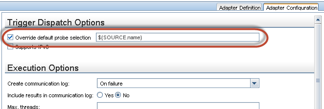
Select the adapter and click the Adapter Configuration tab.
- Under Trigger Dispatch Options, select Override default probe selection.
-
In the box, enter the Probe in one of the following formats:
Probe name The name of the Probe IP address The Probe's IP address—can be defined in either IPv4 or IPv6 format IP,Domain IPv4 format: 16.59.63.86,DefaultDomain
IPv6 format: 2001:0:9d46:953c:34a9:1e6b:f2ff:fffe,CustomDomain
Domain name The domain from which the Probe should be selected.
For example:
-
-
Configure a classpath for a remote process - Optional
For details, see Configure Remote Process Execution.