


Working with Relationships
Many of the relationships between CIs in the
Creating Relationships
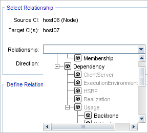
You can create relationships by right-clicking a CI or multiple CIs in the CI Selector pane or the Topology Map and selecting Relate to CI from the shortcut menu. In the Topology Map, you can define a relationship between two CIs in the view by drawing a line between the two, using the Create Relationship ![]() button from the toolbar. Either of these actions opens the Insert Relationship dialog box. For details, see Insert Relationship Dialog Box.
button from the toolbar. Either of these actions opens the Insert Relationship dialog box. For details, see Insert Relationship Dialog Box.
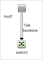
You can create as many relationships as necessary between a CI in the host7 has both a Backbone and a Talk relationship with switch3.
Note If a Running Software CI is related to another CI with a Containment relationship, you cannot create another Containment relationship from the Running Software CI.
Creating Hierarchical Relationships
By attaching one CI to another in IT Universe Manager you create a hierarchical relationship (parent-child) between them, so that one CI is influenced by the other.
Certain relationships defined in this way are restricted to the relationship type usage (if the relationship is between two non-monitoring CIs), or the relationship type Monitored By (if the child CI in the relationship is a monitor type CI); however, other relationship types are used between specific types of CIs. For example, if a relationship is defined between two node CIs, there are several possible relationship types.
Note When you attach a child CI to a parent CI, you are creating that relationship in the
Attaching Existing CIs
You can attach existing CIs using the Insert Relationship dialog box. The dialog box has two modes:
-
Selecting the CIs that you want to attach.
-
Defining the relationship between the original CI and the CIs to attach.
When selecting the CIs to attach, you can select multiple CIs from a view to attach to the original CI. However, all CIs that you want to attach in one operation must have the same relationship type. For example, you cannot attach a CI that uses the relationship usage in the same operation as a CI that uses the relationship Monitored By.
Setting the View Hierarchy
After setting the query node and relationship definitions of a view, you can set a hierarchy for the view. This enables you to define the organizational structure of CIs in the view by displaying selected CIs at different levels. When no hierarchy is defined, the Topology Map or table displays all CIs included in the query results on one level by default. For example, if the query results include nodes and IP Subnets, both CI types are displayed on the same level in the Topology Map or table.
Note The maximum number of CIs that can be displayed in a single layer of the Topology Map is 900. If a view contains a layer with more than 900 CIs, the view is not displayed in the Topology Map until the hierarchy is changed. However, a layer with more than 900 CIs can be displayed in a table in Text mode.
For details on setting the hierarchy, see Setting the View Hierarchy.
Relationship Properties
Relationships have properties, similar to CIs. You can access the Configuration Item Properties dialog box to view the relationship properties from IT Universe Manager by right-clicking the relationship and selecting Properties or by clicking the Properties tab in the Advanced pane. You can also edit the relationship properties if you have the necessary permissions for editing CIs. For details on relationship properties, see Configuration Item Properties Dialog Box.
Note For relationships of type composition connected to a CI of type Node Element or its descendant CI types, relationship properties are not saved. When a TQL query containing such a relationship is run, the default values for the relationship properties are used even if you edited the properties.
Viewing Related CIs
You can view all the CIs related to a selected CI in the topology map. Select a CI in a view and then select the Related CIs tab. The Get Related CIs pane enables you to select the scope of the display. If you select View, the topology map displays only the selected CI and its related CIs in the view (no matter where it is in the view hierarchy). If you select CMDB, it displays the selected CI and all of its related CIs in the
You can also display Related CIs using the Get Related CIs from CMDB dialog box. For details, see Get Related CIs From CMDB Dialog Box.
Deleting Relationships
The Topology Map shows only the relationships for the CIs that are part of the current view; however, the same relationships may also be part of other views. When you delete a relationship in IT Universe Manager, it is deleted from the
When a relationship is deleted, the CI on the other end of the relationship may remain in the view, if it still matches the pattern of the view. However, if the deleted relationship is a composition link, the target CI is deleted with it.
In a perspective-based view, you can remove the CI completely from the view (without deleting it from the
When you delete a relationship that was created by the DFM process, the relationship is restored the next time that DFM runs (if the relationship is still valid), and it reappears in all relevant pattern views.
It can take a few minutes to delete subtrees, or multiple CIs and relationships, from a view.
Inter-Layer Relationships
In certain circumstances, IT Universe Manager displays a relationship between CIs in a layer of a view that does not reflect an actual relationship between the CIs in that layer, but rather a relationship between CIs on deeper layers of the view. Such a relationship is known as an inter-layer relationship.
For example, in the following view, two node CIs are related to each other with a dependency relationship. Each is also related to an IP Subnet by a membership relationship and the view hierarchy is defined such that the nodes are on the layer beneath the IP Subnet.
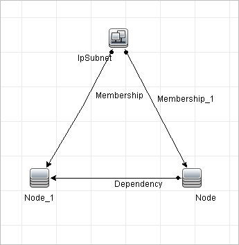
When you consume the view in IT Universe Manager, the relationship between the node CIs (which are under different IP Subnets) is displayed in the higher layer of the view as a relationship between the parent IP Subnets, even though the actual relationship only exists between the CIs in the lower layer of the view. You can double-click the relationship to display the full path between the IP Subnets.
Another form of inter-layer relationship occurs when the same CI appears under more than one parent CI of the same type in the layer above it. In such a case, the child CI and its relationships are duplicated in the view display, due to the hierarchy definition. The relationships of such child CIs result in inter-layer relationships between the parent CIs. This type of inter-layer relationship is known as a duplication metalink.
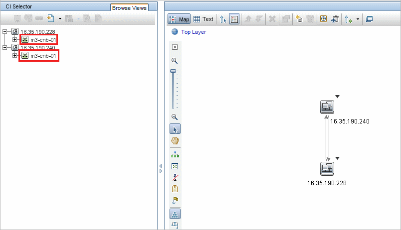
For example, in the following view, a single node CI appears under two IP Subnet CIs in the hierarchy. The node and its children thus appear twice in the view - once under each IP Subnet. Each node is effectively related to the child CIs of the node under the other IP Subnet, which generates an inter-layer relationship between the two IP Subnets.
Inter-layer relationships and duplication metalinks are displayed in gray in the topology map. The following options are available for viewing inter-layer relationships (defined in the View Definition Properties dialog box in Modeling Studio):
-
None. Hide all inter-layer relationships.
-
Inter-Layer. Display inter-layer relationships of the first type, but not duplication metalinks.
-
Full. Display all inter-layer relationships, including duplication metalinks.
A tooltip for the inter-layer relationship displays the inner relationships which it represents. If there is only one inner relationship, the relationship label displays that relationship type. If there are multiple inner relationships, the label becomes Inter-layer and the tooltip displays a list of all the inner relationships. If there are more than ten inner relationships, only the first ten are displayed, and a note indicates that there are more inner relationships.