


SA high availability
This document discusses failover, high availability and load balancing for Server Automation Ultimate Edition.
Note There are two editions of Server Automation, Server Automation Ultimate and Server Automation Standard (Virtual Appliance). This document applies to Server Automation Ultimate.
Server Automation is data center automation software that centralizes and streamlines many data center functions and automates critical areas of your data center’s server management, including:
- Server Discovery
- Operating System Provisioning
- Operating System Patching
- Software Provisioning
- Audit and Compliance
- Application Configuration
- Application Deployment
- Software Compliance
Additional details on these functions can be found in the Server Automation Overview and Architecture Guide. You can use the SA Documentation Library to find the latest version of the guides for your version of SA on the HPE Software Support Online (HPE Passport required).
Designing Server Automation architecture for high availability
Note: This paper does not address backup/restore, monitoring or disaster recovery. All three of these need to be addressed in order to create a fully resilient solution.
The architectures described in the following sections presume that SA is installed using the standard SA Core Configurations documented in the Server Automation
Server Automation can be deployed in multiple configurations which provide different degrees of resiliency. This paper does not address database HA beyond noting that Oracle RAC can be used with SA.
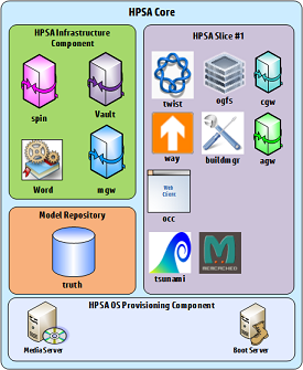
Server Automation components
At the most basic, an SA Core consists of the following components:
- Infrastructure
- Slice#1
- Model Repository (either local or remote)
- OS Provisioning components
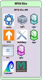
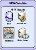
An SA Core can be scaled internally by adding additional Slice components, and externally by adding additional SA Cores and Satellites.
|
|
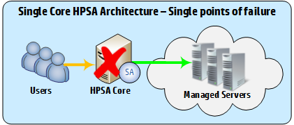
A basic SA deployment consisting of a single SA Core is shown below:
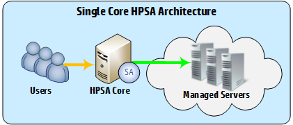
In this design, the SA core is a single point of failure – both user connections and server management will fail if the SA core fails, as shown below.
In-core load balancing
This information is included for troubleshooting purposes; modifying the load balancing configuration is NOT recommended, and typically results in unexpected behaviors and failures.
An SA Core consists of an Infrastructure, Slice#1, Model Repository (either local or remote), OS Provisioning component and one or more additional Slice components.
In a multi-slice configuration, the SA infrastructure component automatically load balances various services across the slices in the core, allowing additional slices to fail transparently.
The following SA Slice components are load balanced between active slices:
|
SA Slice Component |
Load Balancing Mode |
Description |
|---|---|---|
|
Command Center (occ) |
TLS_LC |
Use a sticky TLS session to the slice with the least number of connections |
|
Global File System (hub) |
STICKY |
Use a sticky connection to a randomly selected slice |
|
Secondary Data Access Engine (secondary spin) |
STICKY |
Use a sticky connection to a randomly selected slice |
|
Software Repository (word) |
STICKY |
Use a sticky connection to a randomly selected slice |
|
Web Services Data Access Engine (twist) |
STICKY |
Use a sticky connection to a randomly selected slice |
|
Command Engine (way) |
STICKY |
Use a sticky connection to a randomly selected slice |
If the following Slice components are enabled and fail, the default Software Repository functionality will be used.
|
SA Slice Component |
|
Software Repository Accelerator (tsunami) |
|
Memcache |
SA Multimaster Mesh – Simple core failover
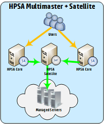
The first HA Architecture that we consider here is a basic Multimaster Mesh, with two SA Cores, and a single satellite.
The primary advantage of this configuration is the ability to continue to manage servers and serve users in the event of a single core failure.
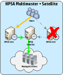
A Satellite has been added in this configuration, as servers which are managed directly by a core will become unreachable if that core fails; satellites can be configured to fail between cores. This ensures that server management can continue if one of the cores fails (Figure 4: SA Multimaster + Satellite - Core Failure).
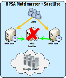
If the Satellite fails, users will still be able to connect to the SA cores, but server management will not be available.
In this configuration, users can connect to either SA core, but must know the address of the core that they wish to connect to in the event of a failure.
|
SA Multimaster + Satellite Failure Conditions |
|
|
|
|
Simple core failover configuration
This section describes the components and additional configuration required to implement this solution.
- Install the First (Primary) Core with a Secondary Core (Multimaster Mesh) as described in the Server Automation
-
Install the SA Satellite as described in the Server Automation
The Satellite Gateway name uniquely identifies the satellite, and is typically something similar to <Satellite Facility Name><number>, eg: SATFACILITY01
- Perform the remaining configuration tasks and finalize the satellite installation.
-
Edit the gateway properties file and modify section 3 as follows:
# 3) This Gateway should have at least one outbound tunnel.
# Please uncomment one the lines below and replace the IP
# and port (i.e., 10.0.0.10:2001) with the IP and TunnelDst
# port for your Core-side Gateway component.
# ip:port:cost:bw (bw in kbits/sec)
opswgw.TunnelSrc=<core1 ip>:2001:100:0:/var/opt/opsware/crypto/opswgw-SA1010SAT01/opswgw.pem
opswgw.TunnelSrc=<core2 ip>:2001:200:0:/var/opt/opsware/crypto/opswgw-SA1010SAT01/opswgw.pem
#opswgw.TunnelSrc=10.0.0.11:2001:200:0:/var/opt/opsware/crypto/opswgw-SA1010SAT01/opswgw.pem
These two lines tell the satellite to create encrypted tunnels to the management gateways on Core1 and Core2, with the ‘100’ and ‘200’ indicating which tunnel will be preferred (the lower number takes priority).
Note Each tunnel MUST have a different priority. Setting the same priority will result in unpredictable failures.
In this case, the configuration means that the satellite will send traffic to Core1 unless Core1 is down. If Core1 is down, the satellite will select the tunnel with the next lowest priority, which would be Core2 in this example.
Note Gateway customizations (i.e. adding a new tunnel to Core 2) should be moved from the opswgw.properties file to the opswgw.custom file (/etc/opt/opsware/opswgw-<gateway_name>/opswgw.custom) to preserve those customizations during a Server Automation upgrade.
- Perform the remaining configuration tasks.
SA Multimaster Mesh – core and satellite failover
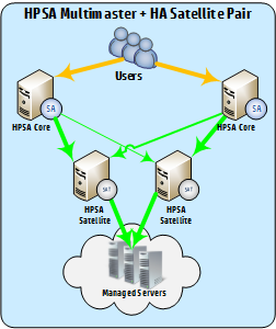
This design improves on the initial SA Multimaster Mesh design through the introduction of an HA Satellite pair in place of the single satellite in SA Multimaster Mesh – Core and Satellite Failover.
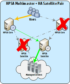
This design ensures that services can continue transparently in the event of a core, satellite, or core and satellite failure.
In this configuration, users can connect to either SA core, but must know the address of the core that they wish to connect to in the event of a failure.
|
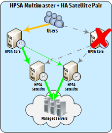
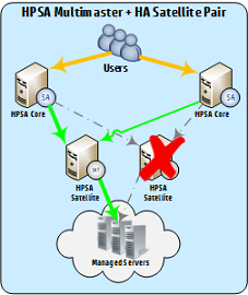
SA Multimaster Mesh – Core or Satellite Failure |
|
|
|
|
|
SA Multimaster Mesh – Core or Satellite Failure |
|
|
Core and satellite failover configuration
This section describes the components and additional configuration required to implement this solution.
- Install the First (Primary) Core with a Secondary Core (Multimaster Mesh) as described in the Server Automation
-
Install the first SA Satellite as described in the Server Automation
The Satellite Gateway name uniquely identifies the satellite, and is typically something similar to <Satellite Facility Name><number>, eg: SATFACILITY01
-
Install the second SA Satellite as described in the Server Automation
The Satellite Gateway name uniquely identifies the satellite, and is typically something similar to <Satellite Facility Name><number>, eg: SATFACILITY02.
-
After the satellite installation is complete, edit the gateway properties file and modify section 3 as follows:
# 3) This Gateway should have at least one outbound tunnel.
# Please uncomment one the lines below and replace the IP
# and port (i.e., 10.0.0.10:2001) with the IP and TunnelDst
# port for your Core-side Gateway component.
# ip:port:cost:bw (bw in kbits/sec)
opswgw.TunnelSrc=<core1 ip>:2001:100:0:/var/opt/opsware/crypto/opswgw-SA1010SAT01/opswgw.pem
opswgw.TunnelSrc=<core2 ip>:2001:200:0:/var/opt/opsware/crypto/opswgw-SA1010SAT01/opswgw.pem
#opswgw.TunnelSrc=10.0.0.11:2001:200:0:/var/opt/opsware/crypto/opswgw-SA1010SAT01/opswgw.pem
These two lines tell the satellite to create encrypted tunnels to the management gateways on Core1 and Core2, with the ‘100’ and ‘200’ indicating which tunnel will be preferred (the lower number takes priority).
Note Each tunnel MUST have a different priority. Setting the same priority will result in unpredictable failures.
Tunnel priority MUST be set to the same values on both satellites.
In this case, the configuration means that the satellite will send traffic to Core1 unless Core1 is down. If Core1 is down, the satellite will select the tunnel with the next lowest priority, which would be Core2 in this example.
Note Gateway customizations (i.e. adding a new tunnel to Core 2) should be moved from the opswgw.properties file to the opswgw.custom file (/etc/opt/opsware/opswgw-<gateway_name>/opswgw.custom) to preserve those customizations during a Server Automation upgrade
- Perform the remaining configuration tasks.
SA Multimaster Mesh – core, satellite and end-user access failover
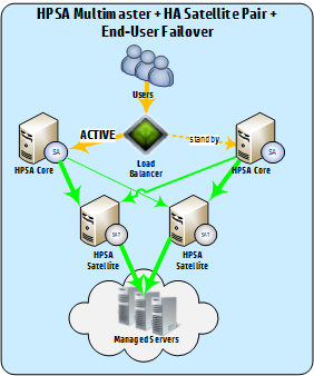
This design builds on the previous SA Multimaster Mesh – Core and Satellite Failover design to include end-user access failover.
Both a single connection point and transparent end-user failover are provided by the use of an external load balancer.
The load balancer MUST be configured as follows, to avoid issues with SA internal replication and load balancing:
- Load balancer MUST be configured to point the SA core Infrastructure server in an active/standby configuration.
- Sticky SSL sessions MUST be configured
HA summary
The following table outlines the HA capabilities available in a single SA Core or SA Multimaster Mesh configuration with the specified SA Components.
|
SA Component |
SA Core |
SA Multimaster Mesh |
|---|---|---|
|
SA Core |
n/a |
Core Failover |
|
+additional slice component bundle instances |
Load Balance* |
Core Failover Load Balance* |
|
+satellites |
|
Satellite Failover between cores |
|
+satellite HA pair(s) |
Agent Failover† |
Core Failover Satellite Failover between cores Satellite Failover Agent Failover† |
|
+additional slice component bundle instances and satellites |
Load Balance* |
Core Failover Satellite Failover between cores Load Balance* |
|
+additional slice component bundle instances and satellite HA pair(s) |
Agent Failover† Load Balance* |
Core Failover Satellite Failover between cores Agent Failover† Load Balance* |
*for certain components
†for agents managed via satellite HPE pair(s)
SA component failure impact
|
|
SA Component |
Failure Result (Core) |
Failure Result (Mesh) |
|---|---|---|---|
|
Model Repository (truth) |
Core failure |
Core failure; Mesh continues |
|
|
Infrastructure |
Primary Data Access Engine (spin) |
Core failure |
Core failure; Mesh continues |
|
Management Gateway (mgw) |
Core failure |
Core failure; Mesh continues |
|
|
Model Repository Multimaster Component (vault) |
Core failure |
Core failure; Mesh continues |
|
|
Software Repository Store (word) |
Core failure |
Core failure; Mesh continues |
|
|
OS Prov |
Media Server |
OS Provisioning failure |
OS Provisioning failure |
|
Boot Server |
OS Provisioning Failure |
OS Provisioning Failure |
|
|
Slice #1 |
Core Gateway / Agent Gateway (cgw / agw) |
Core failure |
Core failure; Mesh continues |
|
Command Center (occ) |
User Access failure |
Core failure; Mesh continues |
|
|
Global File System (ogfs) |
Core failure |
Core failure; Mesh continues |
|
|
Web Services Data Access Engine (twist) |
Core failure |
Core failure; Mesh continues |
|
|
Command Engine (way) |
Job failure / Core failure |
Core failure; Mesh continues |
|
|
Software Repository Accelerator (tsunami) |
n/a |
n/a |
|
|
Memcache |
n/a |
n/a |
|
|
Slice #x |
Core Gateway / Agent Gateway (cgw / agw) |
Slice failure |
n/a |
|
Command Center (occ) |
Slice failure |
n/a |
|
|
Global File System (ogfs) |
Slice failure |
n/a |
|
|
Web Services Data Access Engine (twist) |
Slice failure |
n/a |
|
|
Secondary Data Access Engine (spin) |
Slice failure |
n/a |
|
|
Command Engine (way) |
Slice failure |
n/a |
|
|
Software Repository Accelerator (tsunami) |
n/a |
n/a |
|
|
Memcache |
n/a |
n/a |
|
Sample F5 load balancer configuration
lb.example.com:
wideip {name "lb.example.com"
pool_lbmode rr
partition "Common"
pool "lb.example.com_443"
}
pool {name "lb.example.com_443"
ttl 30
monitor all "https"
preferred ratio
alternate ratio
partition "Common"
member 10.100.1.10:443 ratio 100
member 10.100.2.10443 ratio 0
}