Use Case - End-to-End Database Import
Requirement
The IT Service Manager provides, daily, the following primitive metrics for the management or orders by employees:
- Cost: The total cost of orders that are incurred.?? do you mean fulfilled orders or pending orders???
- Order: The total number of orders that are incurred.
The data provided by these metrics are presented in two database tables:
The Employee table includes the Employee_No, Employee_Name, Employee_Age, and Hire_Date columns.
The Orders table includes the Order_ID (unique), Cost, Order_Date, and Employee_No columns.
Design
The IT Service Manager would like to automatically provide meaningful data.
The way to accomplish this is as follows:
- A Scorecard is created for the IT Service Manager.
- The Name of the company that requested the order is configured as a Perspective.
- Each Employee corresponds to an Objective.
- KPIs for COST and ORDER are configured beneath each Objective.
- Breakdowns are configured (Order ID) for each KPI.
Tasks required to accomplish the scenario
- Create new target, integration and source model, finish the ETL mapping in the engineer diagram.
- Generate the ETL artifacts.
- Deploy Content Pack.
- Run ETL.
- Create Context.
- Create KPI and Dashboard.
Create the new target, integration and source model, finish the ETL mapping in the engineer diagram.
-
IDE Setup:
Install the contents of the IDE DVD. The IDE can be also downloaded from HP Live Network (HPLN) and contains:
- IDE: Unzip the file and double-click eclipse/eclipse.exe to run the IDE Eclipse application.
- IDE Content: Contains the OOTB Content Packs.
-
Open the Eclipse IDE:

-
Change perspective to BA IDE:

-
(If not done yet) Import the Core CP project into the IDE.
-
Right click at the Package Explorer and select Import.
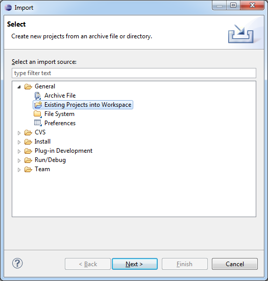
-
Browse for the cp-core directory under the workspaces/ide_workspace directory (provided) and hit OK:
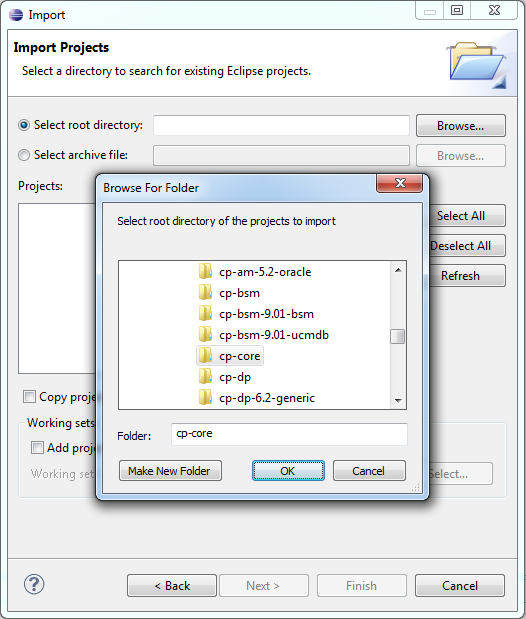
-
Click Finish to import the project.
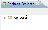
-
-
Create the Integration Content Pack and link it to the Core CP.
-
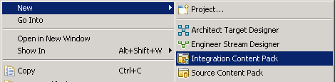
Right-click the relevant Package Explorer and select New > Integration Content Pack.
-
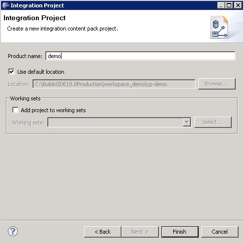
Specify the project name demo and click Next.
-
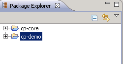
In the Target Content Pack Reference window, check cp-core and click Finish.
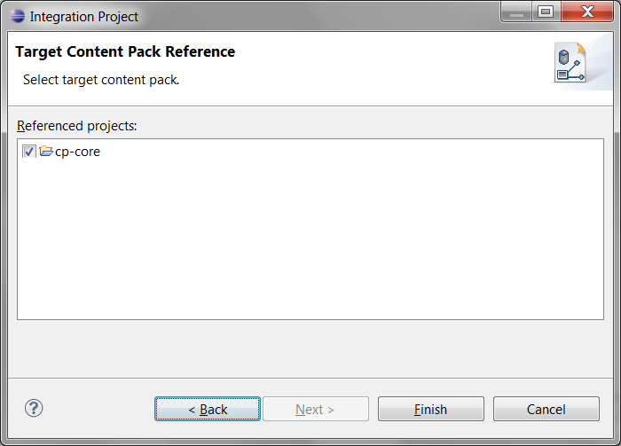
The Integration Content Pack is created.
-
-
Create the Source Content Pack and link it to the Integration CP.
-
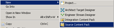
Right click the Package Explorer and select New > Source Content Pack.
-
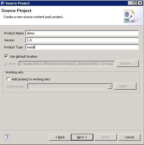
In Project Name specify demo. In the Version specify 1.0 and in RDBMS specify mssql (1.0 is the version of demo, mssql is the type of the data source from which the data is extracted, in this case the MS SQL Server) and click Next.
-
In the Integration Content Pack Reference window, select cp-demo and click Finish.
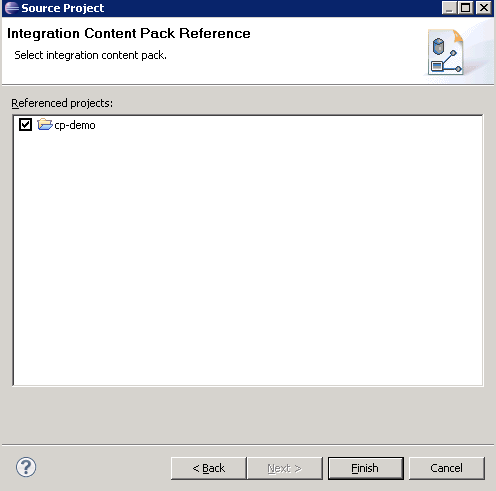
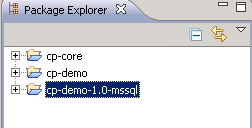
The Source Content Pack is now created
-
-
Create the empty project for storing the Engineering Context Diagram.
-
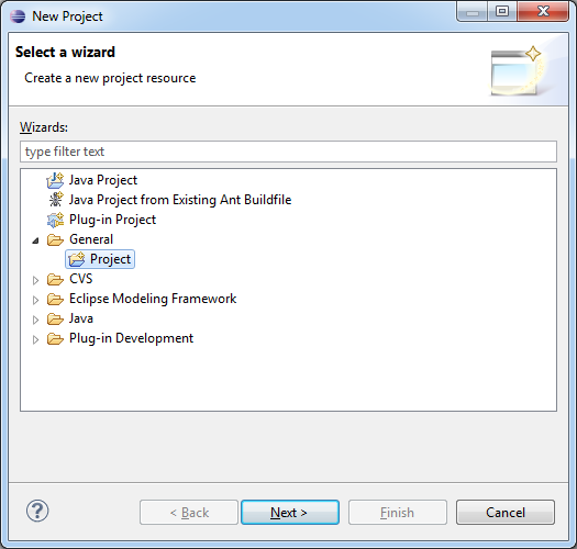
Right click at the Package Explorer and select New > Project, expand the General directory, select Project and click Next.
-
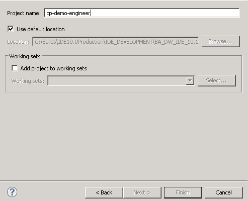
Enter the cp-demo-engineer project name and click Next.
-
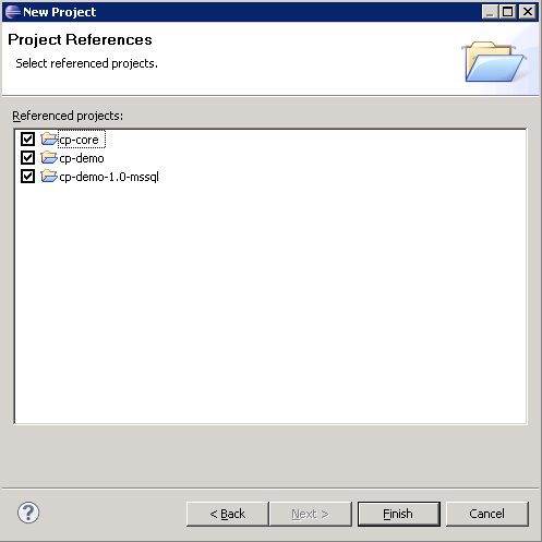
In the Project References panel, select cp-core ,cp-demo, and cp-demo-1.0-mssql.
-
-
Create the empty project for storing the Architect Context Diagram.
-
Right click the relevant Package Explorer and select New > Project, expand the General directory, select Project and click Next.
-
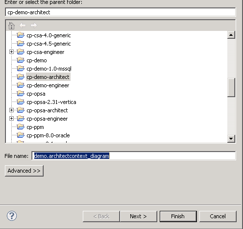
Enter the cp-demo-architectproject name and click Next.
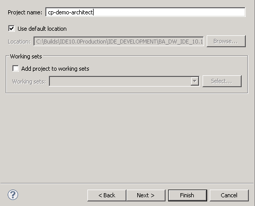
- In the Referenced Projects panel, select cp-core and click Finish
-
-
Create the Architect Context.
-
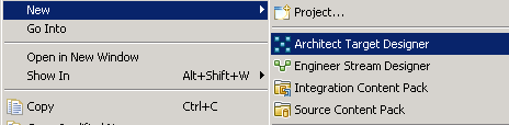
Right click the cp-demo-architect project and select New > ArchitectTarget Designer.
-
Enter the demo.architectcontext_diagram file name and click Next.
-
Select the cp-core target content pack and click Next.
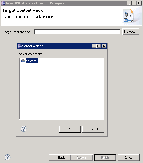
The architect diagram is created and opened automatically.
-
-
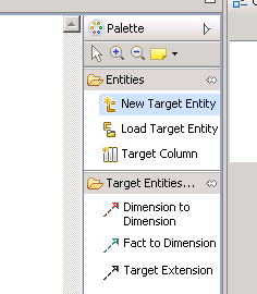
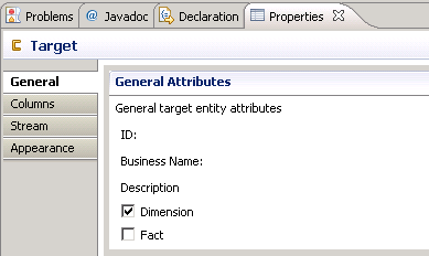
Design the target model in the architect context designer.
In this case, you create one new dimension entity and one new fact entity. The fact entity has a reference key with the dimension entity.
-
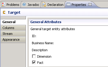
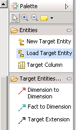
First, create the dimension entity. Click the New Target Entity button and click in the middle of canvas to place it.
-
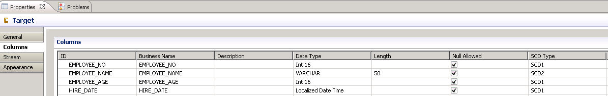
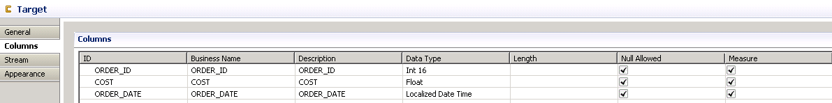
Define the entity attribute in the General tab, and define the column attribute in the Columns tab.
-
Second, create the fact entity in the same architect context by clicking the New Target Entity button and clicking in the middle of canvas to place it.
-
Define the entity attribute in the General tab, and define the column attribute in the Columns tab as above.
-
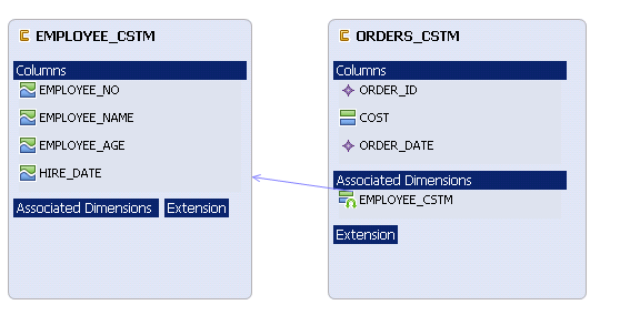
Click the Fact to Dimension button, and drag the arrow from Fact entity to Dimension entity to make the reference between Fact and Dimension entity.
-
Click the Load Target Entity button, and click in the middle of canvas to place it to load the Period_Dim OOTB entity .
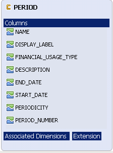
-
Click the Fact to Dimension button, and drag the arrow from the Fact entity to the Period Dimension entity to make the reference between Fact and Period Dimension entity.
-
-
Create the Engineering Context.
-
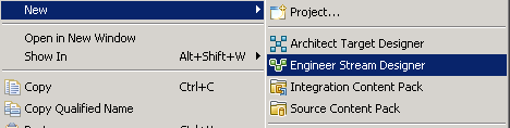
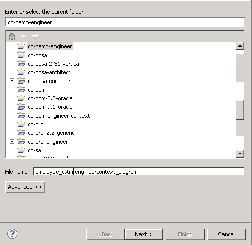
Right click the cp-demo-engineer Project and select New >EngineerStream Designer.
-
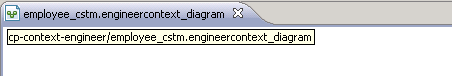
Change the file name to employee_cstm.engineercontext_diagram and click Next.
-
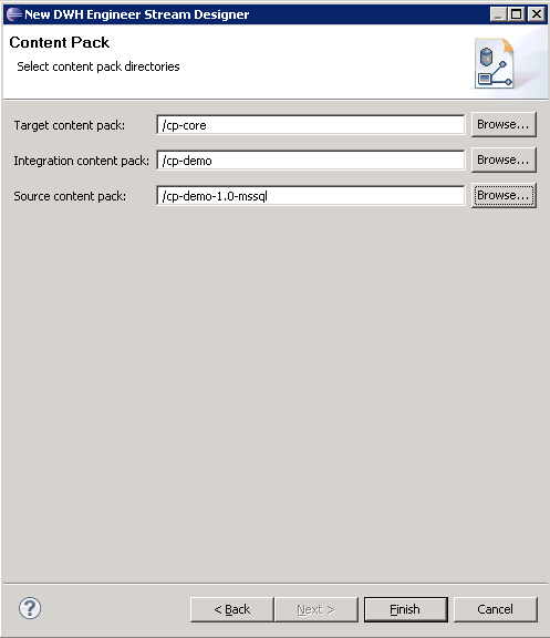
Select cp-core as the Target Content Pack, cp-demo as the Integration CP directory and cp-demo-1.0-mssql as the Source CP directory and click Finish.
-
The engineering context diagram is created and is automatically opened.
-
-
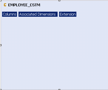
Open the existing Target Entity which you have created before.
-
Click Load Target Entity on the Palette and click in right part of the canvas to place it.
-
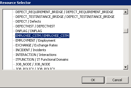
In the Resource Selector dialog, unfold CORE, select EMPLOYEE_CSTM entity and click OK.
-
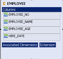
The EMPLOYEE target entity contains all the relevant fields added in the architect diagram.
-
-
Create a new Integration entity
-
Click New Integration Entity on the Palette and click in the middle of the canvas to place it.
-
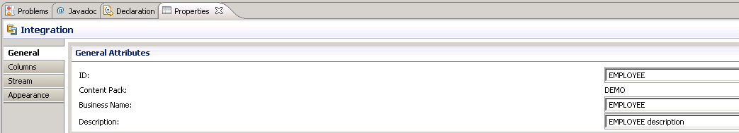
Change the name to EMPLOYEE.
-
-
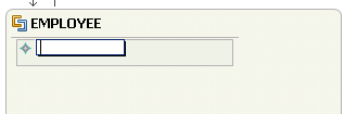
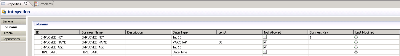
Create the Integration entity fields.
-
Add the new field by clicking Integration Column in the Palette and clicking the EMPLOYEE entity to place the field.
-
Edit the integration attribute in the General tab and edit the column attribute in the Columns tab. Define the Business key and Last Modified date for the integration entity.
-
-
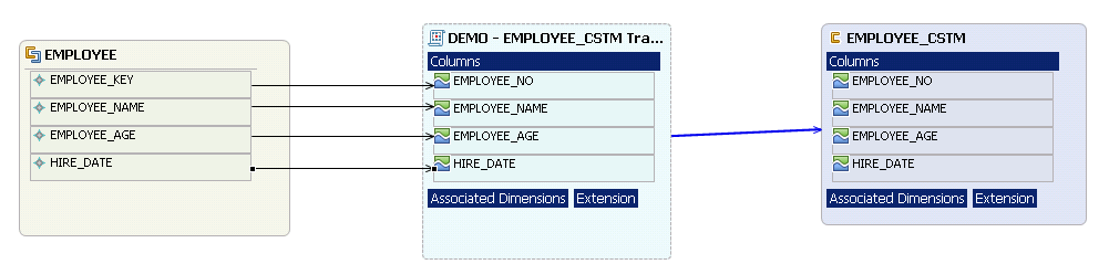
Map the Integration entity fields to Target entity fields.
- Click Column Mapping under Transformation section in the Palette.
- Click the field in the integration entity and drag & drop the arrow on the relevant field in the target entity.
-
The transformation entity should be opened automatically, then you need to drag the arrow from the integration to transformation entity for the rest field which need to be mapped.
-
Create the Source entity.
-
Click New Source Entity in the Source Entity section on the Palette and then click on the canvas to place it.
-
-
Link the Source Entity to the Integration entity.
- Click Source to Integration Relation in the SourceEntity section of the Palette.
- Link the newly created source entity with the EMPLOYEE integration entity by dragging the arrow from the Source Entity name to EMPLOYEE Integration Entity name.
The source entity is automatically renamed to DEMO.1.0.MSSQL.EMPLOYEE
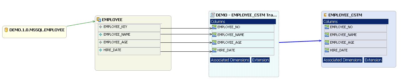
- In this use case, the integration column name is same as the data source, so you don’t need to modify the source entity, but in real projects, it is usually not like that. You can edit the attribute in source entity General tab and Columns tab.
- Click Save All on the Tools panel.
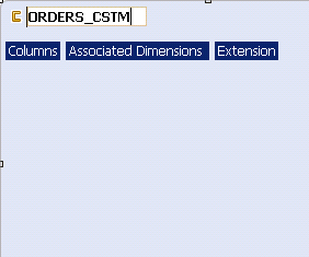
- Right click the cp-demo-engineer project and select New > Engineer > Stream Designer.
-
Change the file name to orders_cstm.engineercontext_diagram and click Next .
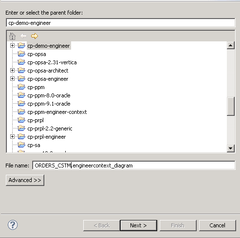
-
Select cp-core as the Target Content Pack, cp-demo as the Integration CP directory, cp-demo-1.0-mssql as the Source CP directory and click Finish.
-
The engineering context diagram is created and is automatically opened.
-
Click Load Target Entity on the Palette and click in right part of the canvas to place it.
- Click Load Target Entity on the Palette and click in right part of the canvas to place it.
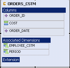
-
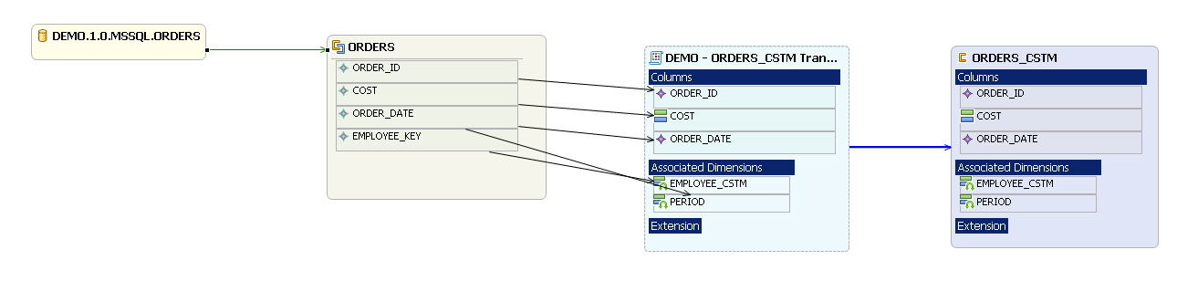
In the Resource Selector dialog, unfold CORE, select ORDERS_CSTM entity and click OK.
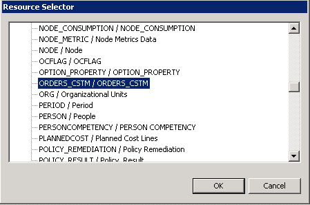
-
The ORDERS target entity contains all the relevant fields added in the architect diagram.
-
Create a new Integration entity
-
Click New Integration Entity on the Palette and click in the middle of the canvas to place it.
-
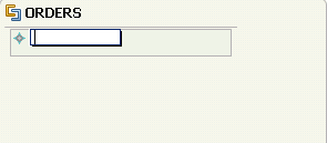
Change the name to ORDERS

-
-
Create the Integration entity fields.
-
Add the new field either by clicking Integration Column in the Palette and clicking the EMPLOYEE entity to place the field.
-
Edit the integration attribute in the General tab and edit the column attribute in the Columns tab. Define the Business key and Last Modified date for the integration entity.
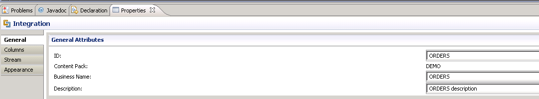
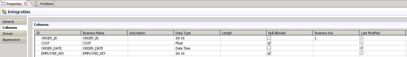
-
-
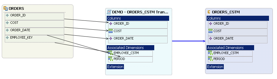
Map the Integration entity fields to Target entity fields.
-
Click Column Mapping under Transformation section in the Palette.
-
Click the field in the integration entity and drag & drop the arrow on the relevant field in the target entity.
-
The transformation entity should be opened automatically, then you need to drag the arrow from the integration to transformation entity for the rest field which need to be mapped.
-
-
Create the Source entity.
-
Click New Source Entity in the Source Entity section on the Palette and then click on canvas to place it.
-
-
Link the Source Entity to the Integration entity.
-
Click Source to Integration Relation in the SourceEntity section of the Palette.
-
Link the newly created source entity with ORDERS integration entity by dragging the arrow from the Source Entity name to ORDERS Integration Entity name.
-
The source entity is automatically renamed to DEMO.1.0.MSSQL.ORDERS
-
- In this use case, the integration column name is same as the data source, so you don’t need to modify the source entity, but in a real project ,it is different and you can edit the attribute in the source entity General tab and Columns tab.
- Click Save All button on the Tools panel.
Generate the ETL artifacts
-
Generate the ETL metadata.
-
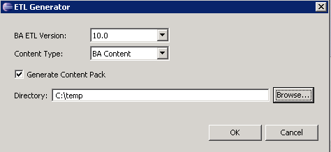
Click the ETL Gen button under DW Content on the Tools panel to generate ETL artifacts, and don’t forget to open both engineering diagrams ORDERS_CSTM and EMPLOYEE_CSTM to generate one by one.

-
Check the Generate Content Pack checkbox at the first time when you generate a new Content Pack, and input path and directory where you want to save the ETL files and click OK
-
Deploy content pack
-
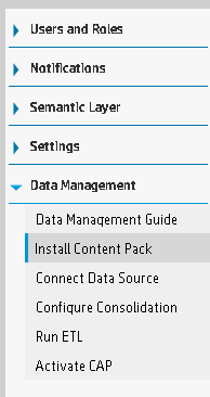
Move the two directories CORE and DEMO from the C:\temp directory that was generated by IDE to the $BTOA_HOME\ContentPacks\ directory.
-
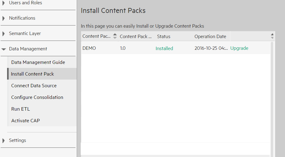
Log in the portal, and install the Demo CP in Install Content Pack.
Run ETL
-
Log in to your env, open the Microsoft SQL Server Management Studio, create a database named DEMO, then execute the below SQL in the studio .
IFOBJECT_ID('employee')ISNOTNULLDROPTABLE employee;CREATETABLE dbo.employee(employee_key INTEGER, employee_name VARCHAR(50), employee_age INTEGER, hire_date DATETIME);
INSERTINTO dbo.employee(employee_key,employee_name,employee_age,hire_date)
VALUES(1,'Monica',25,'2015-01-01 01:01:01.000'),
(2,'Rachel',25,'2015-01-01 01:01:01.000'),
(3,'Joey',25,'2015-01-01 01:01:01.000');

IFOBJECT_ID('orders')ISNOTNULLDROPTABLE orders;
CREATETABLE dbo.orders(order_id INTEGER,employee_key INTEGER,cost DECIMAL(12,4),order_date DATETIME);
insertinto dbo.orders(order_id,employee_key,cost,order_date)
VALUES(100,1,20,'2015-01-01 01:01:01.000'),
(101,2,30,'2015-01-01 01:01:01.000'),
(102,3,40,'2015-01-01 01:01:01.000'),
(103,1,20,'2015-02-01 01:01:01.000'),
(104,2,30,'2015-02-01 01:01:01.000'),
(105,3,40,'2015-02-01 01:01:01.000'),
(106,1,20,'2015-03-01 01:01:01.000'),
(107,2,30,'2015-03-01 01:01:01.000'),
(108,3,40,'2015-03-01 01:01:01.000'),
(109,1,50,'2015-04-01 01:01:01.000'),
(110,2,150,'2015-04-01 01:01:01.000'),
(111,3,40,'2015-04-01 01:01:01.000'),
(112,3,40,'2015-04-01 01:01:01.000'),
(113,1,50,'2015-05-01 01:01:01.000'),
(114,2,150,'2015-05-01 01:01:01.000'),
(115,3,40,'2015-05-01 01:01:01.000'),
(116,3,40,'2015-05-01 01:01:01.000'),
(117,1,50,'2015-06-01 01:01:01.000'),
(118,2,30,'2015-06-01 01:01:01.000'),
(119,2,40,'2015-06-01 01:01:01.000'),
(120,3,40,'2015-06-01 01:01:01.000'),
(121,1,50,'2015-07-01 01:01:01.000'),
(122,2,30,'2015-07-01 01:01:01.000'),
(123,2,40,'2015-07-01 01:01:01.000'),
(124,2,40,'2015-07-01 01:01:01.000'),
(125,1,50,'2015-08-01 01:01:01.000'),
(126,1,30,'2015-08-01 01:01:01.000'),
(127,2,40,'2015-08-01 01:01:01.000'),
(128,2,40,'2015-08-01 01:01:01.000'),
(129,1,10,'2015-09-01 01:01:01.000'),
(130,2,20,'2015-09-01 01:01:01.000'),
(131,3,30,'2015-09-01 01:01:01.000'),
(132,1,20,'2015-10-01 01:01:01.000'),
(133,2,20,'2015-10-01 01:01:01.000'),
(134,3,40,'2015-10-01 01:01:01.000'),
(135,1,20,'2015-11-01 01:01:01.000'),
(136,2,30,'2015-11-01 01:01:01.000'),
(137,3,40,'2015-11-01 01:01:01.000'),
(138,1,20,'2015-12-01 01:01:01.000'),
(139,2,30,'2015-12-01 01:01:01.000'),
(140,3,10,'2015-12-01 01:01:01.000'),
(141,1,20,'2016-01-01 01:01:01.000'),
(142,2,20,'2016-01-01 01:01:01.000'),
(143,3,80,'2016-01-01 01:01:01.000'),
(144,3,10,'2016-01-01 01:01:01.000'),
(145,1,20,'2016-02-01 01:01:01.000'),
(146,2,20,'2016-02-01 01:01:01.000'),
(147,3,20,'2016-02-01 01:01:01.000'),
(148,3,10,'2016-02-01 01:01:01.000'),
(149,1,10,'2016-03-01 01:01:01.000'),
(150,2,30,'2016-03-01 01:01:01.000'),
(151,3,40,'2016-03-01 01:01:01.000'),
(162,1,10,'2016-10-01 01:01:01.000'),
(163,2,30,'2016-10-01 01:01:01.000'),
(164,3,40,'2016-10-01 01:01:01.000');
Now, you have the demo data source database.
-
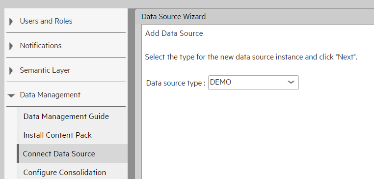
Log in the portal,click the Connect Data Source tab to create the connection between ITBA with the demo database.
-
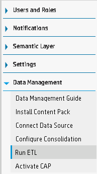
Go to Run ETL, you can run ETL manually or on schedule.
Create Context
-
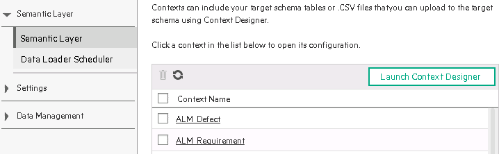
Log on to ITBA portal, go to ADMIN > Semantic Layer, and click Launch Context Designer.
- Click Create New Context.
-
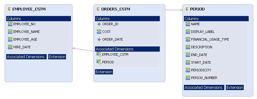
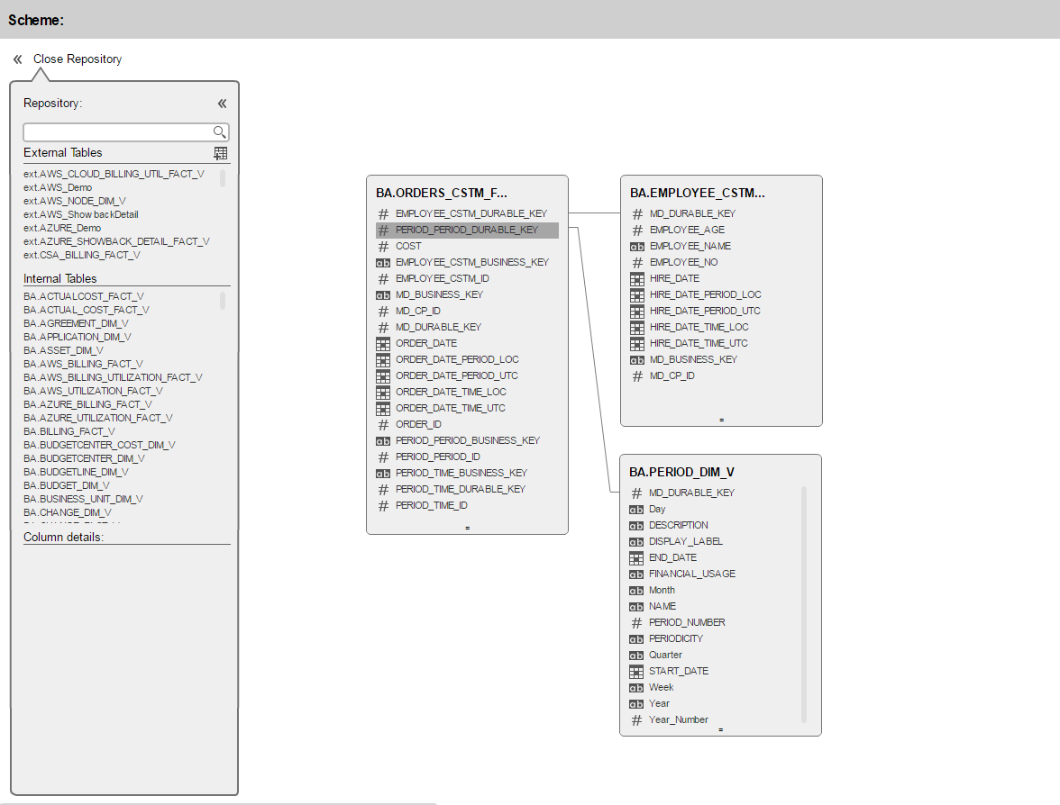
Drag the target entities from internal tables to the canvas, and connect fact entity ORDERS_CSTM and dimension entity EMPLOYEE_CSTM with field ORDERS_CSTM.EMPLOYEE_CSTM_DURABLE_KEY and EMPLOYEE_CSTM.MD_DURABLE_KEY. Connect fact entity ORDERS_CSTM and dimension entity PERIOD with field ORDERS_CSTM.PERIOD_PERIOD_DURABLE_KEY and PERIOD.MD_DURABLE_KEY.
-
Drag the entities from canvas to the Entities panel in the right side, and you can create alias for each entity or even field, and you can remove the field which you don’t want to expose.
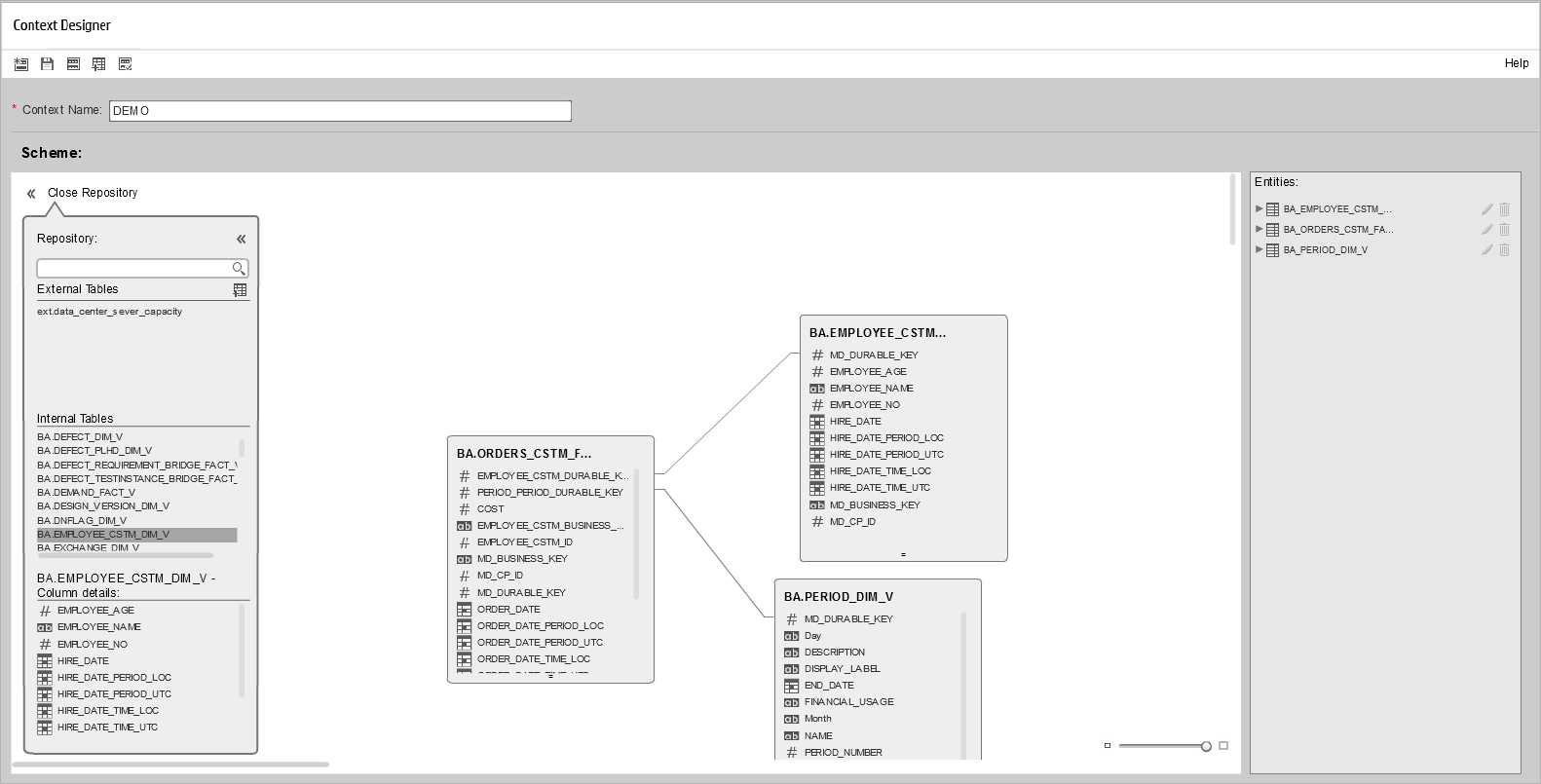
- Save the context.
Create KPI and Dashboard
-
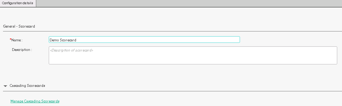
Go to STUDIO, and right click Active KPIs, and select Create New > Scorecard.
-
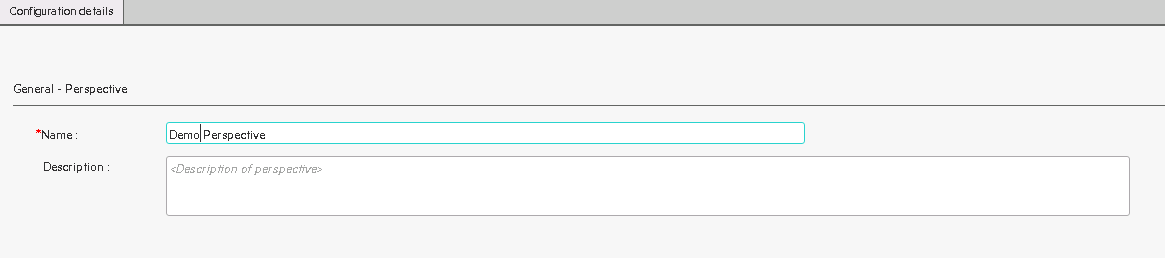
Right click Demo Scorecard under Active KPIs in the left panel, select Create New > Perspective.
-
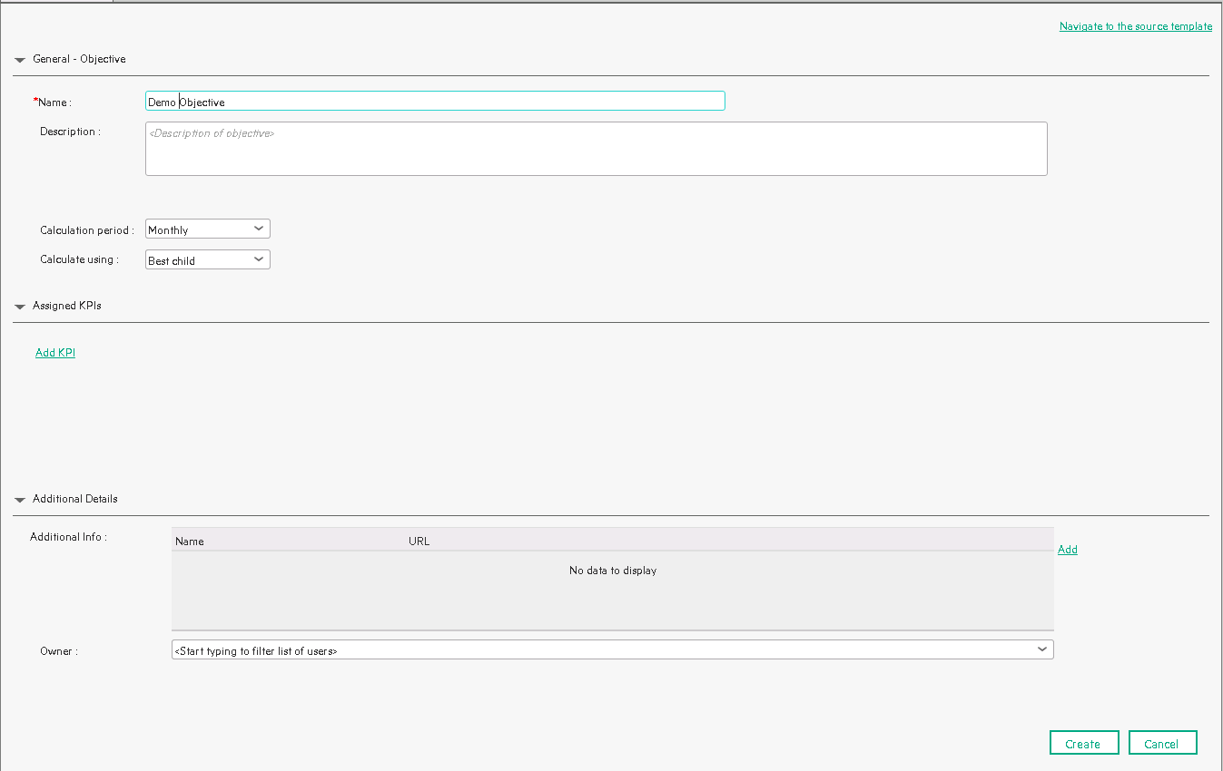
Right click Demo Perspective under Demo Scorecard, select Create New > Objective, you can choose Calculation period and Calculate using. In this case, we just use default configuration.
-
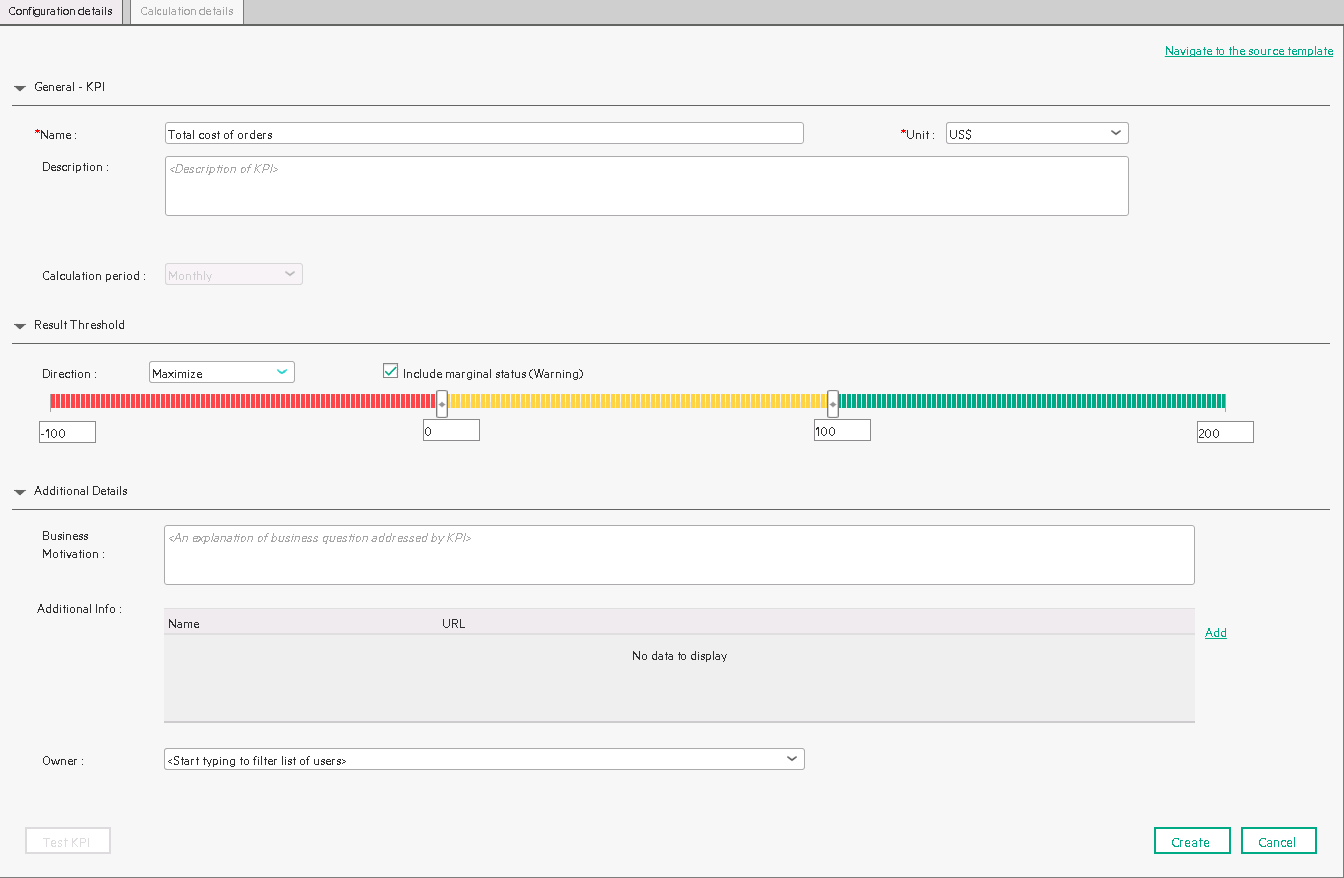
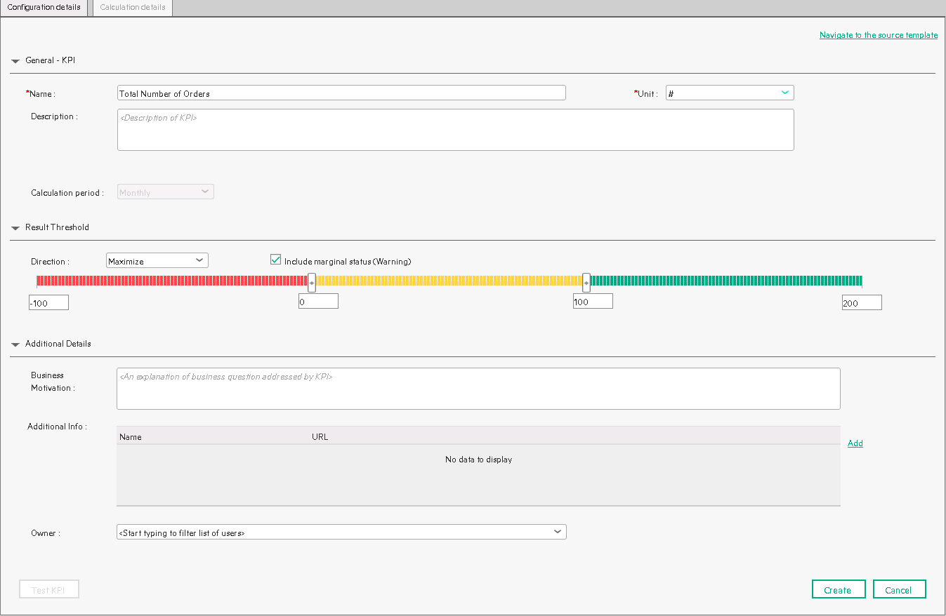
Right click Demo Objective, select Create New > KPI to create two demo KPIs: the total cost of order that are incurred and the total number of order that are incurred. Go to Configuration details to choose US$ as the unit and choose Threshold direction as Maximize. You can adjust the threshold value as you require, in this case, we use default value. Go to Calculation details to select business context and define the KPI formula. And define the Total number of Orders KPI like the previous one.
- Right click Demo Scorecard, select Calculation options > Recalculate to calculate the context Demo. And you can go to Calculation monitoring to monitor the state of context calculation.
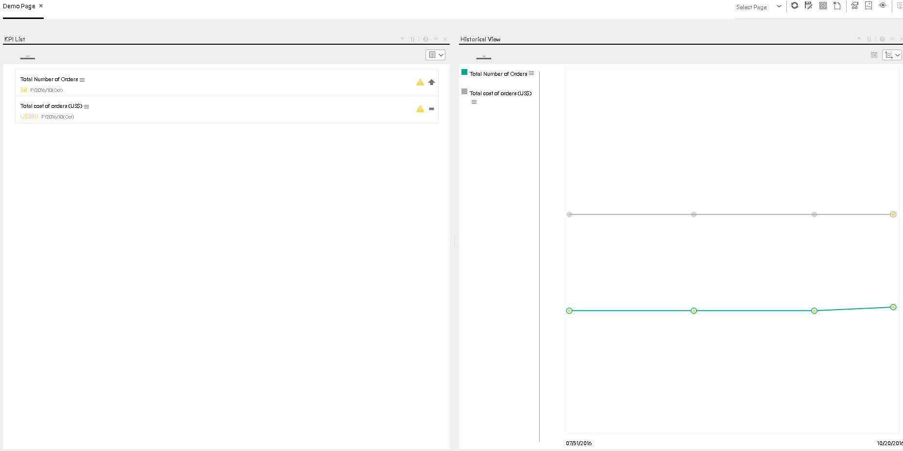
-
Go to the home page to define the dashboard, Click New Page at the right top corner, click Split in the middle of canvas, click add component to choose the b component. Add add both KPIs to the first component. Click Add component to choose Historical View and add both KPIs to this component and save this page.