
Searching the Help
To search for information in the Help, type a word or phrase in the Search box. When you enter a group of words, OR is inferred. You can use Boolean operators to refine your search.
Results returned are case insensitive. However, results ranking takes case into account and assigns higher scores to case matches. Therefore, a search for "cats" followed by a search for "Cats" would return the same number of Help topics, but the order in which the topics are listed would be different.
| Search for | Example | Results |
|---|---|---|
| A single word | cat
|
Topics that contain the word "cat". You will also find its grammatical variations, such as "cats". |
|
A phrase. You can specify that the search results contain a specific phrase. |
"cat food" (quotation marks) |
Topics that contain the literal phrase "cat food" and all its grammatical variations. Without the quotation marks, the query is equivalent to specifying an OR operator, which finds topics with one of the individual words instead of the phrase. |
| Search for | Operator | Example |
|---|---|---|
|
Two or more words in the same topic |
|
|
| Either word in a topic |
|
|
| Topics that do not contain a specific word or phrase |
|
|
| Topics that contain one string and do not contain another | ^ (caret) |
cat ^ mouse
|
| A combination of search types | ( ) parentheses |
|


![]()
![]()

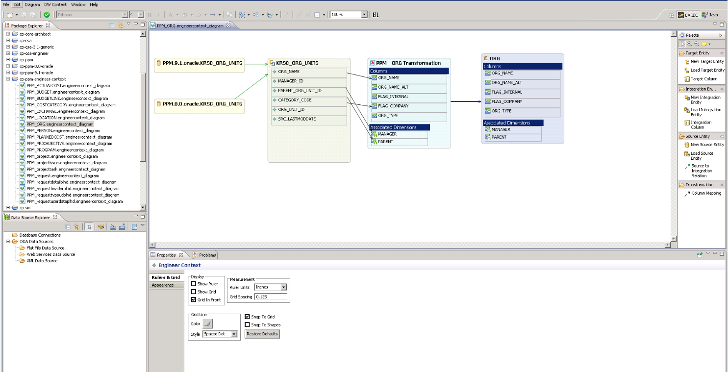
The Engineer Stream Designer enables you to define the integrations and how they are transformed and connected. This view defines the mapping relations for the entity from the source to the target. You can create new integrations based on graphical diagrams, using the Engineer Stream Designer in the IDE tool.
Note Make sure you have selected the IDE perspective before beginning to work on your designer diagram.
In the IDE main page, select File > New > Other > DWH IDE Wizards > Engineer Stream Designer.

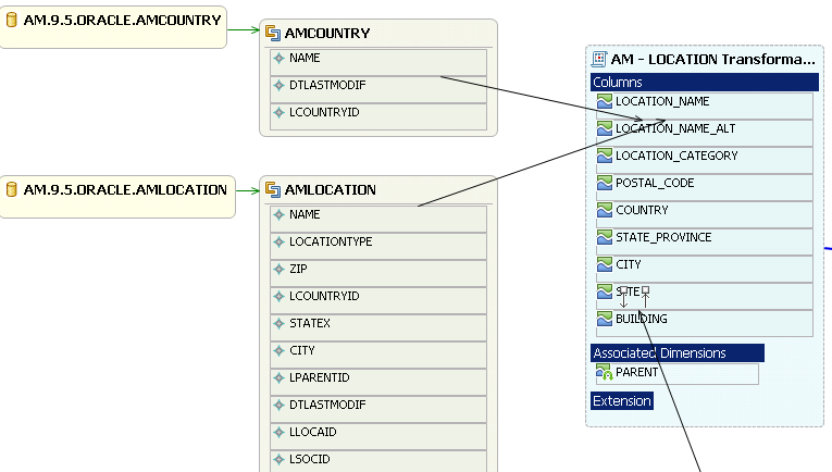
The Engineer Stream Designer enables you to extend and add content from the Integration and Source Content Packs into the target model. Using a new or existing Target entity, you can add new or existing content from the Integration and Source entities. You then perform transformation and Source Integration mapping for new and pre-loaded entities. The Source, Integration and Target entities are mapped using the Transformation Mapping connector, which creates a new mapping entity. All further mapping is done to the new entity in order to complete the Target model.
Note All Source entities must be connected to an Integration entity.
Entities in the Engineer Stream Designer are mapped as follows:
-
Source Entity: Mapping to the correct source, meaning the version the data is extracted from.
-
Integration Entity: Contains the mapping of all fields.
-
Target Entity: Several consolidation entities can be consolidated into one entity.
It is recommended to map from the Source to the Target.
 Source Extractors
OOTB set of existing supported extractors are:
-
Generic Extractors
-
DB Extractor: Supports MSSQL, Oracle and MySQL databases.
-
File Extractor: Supports general CSV file.
-
-
Source Specific Extractor
The supported extractors for the OOTB Content Packs are as follows:
Content Pack Extractor Type PPM(Oracle) DB SM(MSSQL, Oracle, DB2) DB ALM REST API CSA REST API AWS SDK AWSCW SDK AM DB SA DB VPV "REST API" AZURE "REST API" Connecting to the integration:
ETL Gen templates in the back-end generate integration templates which utilize Data Collection Service (DCS). Load the Source metadata to the IDE and then map it to the correct consolidation entity in the relevant fields. To create a custom DCS extractor, see the ..
Important Information
Note Creating new Target entities with Associated Dimensions can only be done in the Architect Target Designer.
Recommended
When you generate ETL artifacts with IDE, if you just put the source and integration entities in the engineer diagram, but do not map any columns with target attributes (no associated dimensions) from source to target (Left to Right), the IDE does not generate the data model correctly, and the ConsolidationReferences in the Extraction model is incomplete.
It is recommended to map at least one column to the target attributes for every integration entity.

Create a new Engineer Stream Designer in the IDE
-
In the IDE main page, select File > New > Other > DWH IDE Wizards > Engineer Stream Designer and click Next.
-
Enter or select the parent directory and enter the file name for the Engineer Stream Designer diagram - make sure you do not change the suffix of the file name - and click Next.
-
Select the Target, Integration, and Source Content Pack directories and click Finish.
Define a new Target entity
-
In the Engineer Stream Designer, in the palette area, select New Target Entity and click on the canvas.
-
Name the entity.
-
Add relevant columns to the entity.
-
Click
 Save.
Save.
Load an existing Target entity
-
In the Engineer Stream Designer, in the palette area, select Load Target Entity and click on the canvas. The Resource Selector dialog box opens.
-
Select an entity. The entity is displayed with all of the previously added columns and dimensions.
-
Click
Save.
Define a new integration entity
-
In the Stream Designer, in the palette area, select New Integration Entity in the Integration section and click on the canvas. An integration entity is displayed.
-
Enter a name. The name can be up to 44 characters. An Integration entity is created.
-
Click Integration Column to add a column to the entity.
-
Perform mapping if required.
-
Click
Save.
Load an existing integration entity
-
In the Stream Designer, in the palette area, select Load Integration Entity in the Integration section and click on the canvas. The Resource Selector dialog box opens.
-
Select an entity. The entity is displayed with all of the previously added mappings.
Define a new source entity
-
In the Engineer Stream Designer, in the palette area, select New Source Entity in the Source section and click on the canvas. A Source entity is displayed.
-
Click Source-Integration Relation and drag the display arrow from the Source entity to an Integration entity. All columns from the Integration entity are copied to the Source entity with default values.
-
Click
Save. Note The Source-Integration Relation tool only enables you to link Source entities to Integration entities of the same product (content pack). For example, a Source entity from cp-sm-9.4-dbdict-mssql can only be linked to Integration entities from cp-sm and not cp-ppm.
Load an existing source entity
-
In the Engineer Stream Designer, in the palette area, select Load Source Entity in the Source section and click on the canvas. The Resource Selector dialog box opens.
-
Select an entity. The entity is displayed with its mapped integration entity.
Add a column
-
In the Engineer Stream Designer, in the palette area, select Target Column or Integration Column.
-
Click in the Column area of your entity and enter the Column ID in the text box.
The column is added to the entity.
- Click Save.
Note Source data is replicated from the integration entity. If you add or delete columns from the Integration, however, it is not automatically done in the Source.
To add: Once you have added the column, delete the mapping link and re-map from the Source to Integration.
To delete: Right-click the deleted column, delete the mapping link and re-map from the Source to Integration.
Alternatively, you can use the Quick Fix mechanism on the error that appears in the Problems tab. For details, see Manage Validations.
Map from the Integration to Target
Once you have added columns to the Integration entity you can perform SSI mapping.
-
In the Engineer Stream Designer, in the palette area, click Column Mapping in the Relations section to map the Integration to the Target entity.
-
Drag the arrow from the Integration column to the Target column.
-
After you have performed the first SSI mapping, a transformation SSI entity is created to which you can perform further mapping. Any integration entity from the same CP that should be mapped to this Target, must be mapped to the transformation entity.
-
Click
Save.Note If an Integration column is already mapped to a Target column, you cannot perform further mapping from the same Content Pack.
Two Integration entity columns from the same Content Pack cannot be mapped to the same Target entity column.

|
UI Element |
Description |
|---|---|
| Target Entity |
|
| Integration Entity |
Contains the following Integration entity options:
|
| Source Entity |
Contains the following Source entity options:
|
| Transformation |
Click to map the displayed entities.
|
 New Target Entity.
  Load Target Entity. Opens the Resource Selector dialog box. Select the relevant entity for your model.
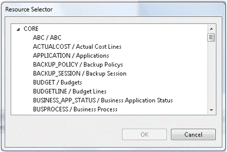
 Target Column.
  New Integration Entity. Select to display a new Integration entity.
 Load Integration Entity. Opens the Resource Selector dialog box. Select the relevant entity for your model.
 Integration Column.
  New Source Entity. Select to display a new Source entity.
 Load Source Entity. Opens the Resource Selector dialog box.Select the relevant entity for your model.
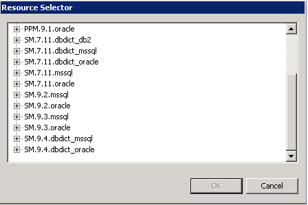
To view the Properties tab, right-click on the specific entity and click Show Properties View.
Note Properties data is replicated in the Integration and Source columns. If you add or delete columns from the Integration, however, it is not automatically done in the Source.
To add: Once you have added the column in the properties tab, delete the mapping link and re-map from the Source to Integration.
To delete: Right-click the deleted column, delete the mapping link and re-map from the Source to Integration.
|
UI Element |
Description |
|---|---|
| General tab |
Displays the General entity attributes. |
| Columns tab |
Displays column information:
|
To view the Properties tab, right-click on the specific entity and click Show Properties View.
|
UI Element |
Description |
|---|---|
| General tab |
General attributes:
Data Source SQL Clauses:
|
| Columns tab |
Displays column information. The Source entity receives all of the Integration entity properties.
|
For details on the Properties for Target entities, see Properties tab for Target entity and specific fields
For details on the Properties tab for Associated Dimensions, see Properties tab for Associated Dimensions.
We welcome your comments!
To open the configured email client on this computer, open an email window.
Otherwise, copy the information below to a web mail client, and send this email to SW-Doc@hpe.com.
Help Topic ID:
Product:
Topic Title:
Feedback: