There are two types of diagrams in the IDE:
- Architect Target Designer
- Engineer Stream Designer
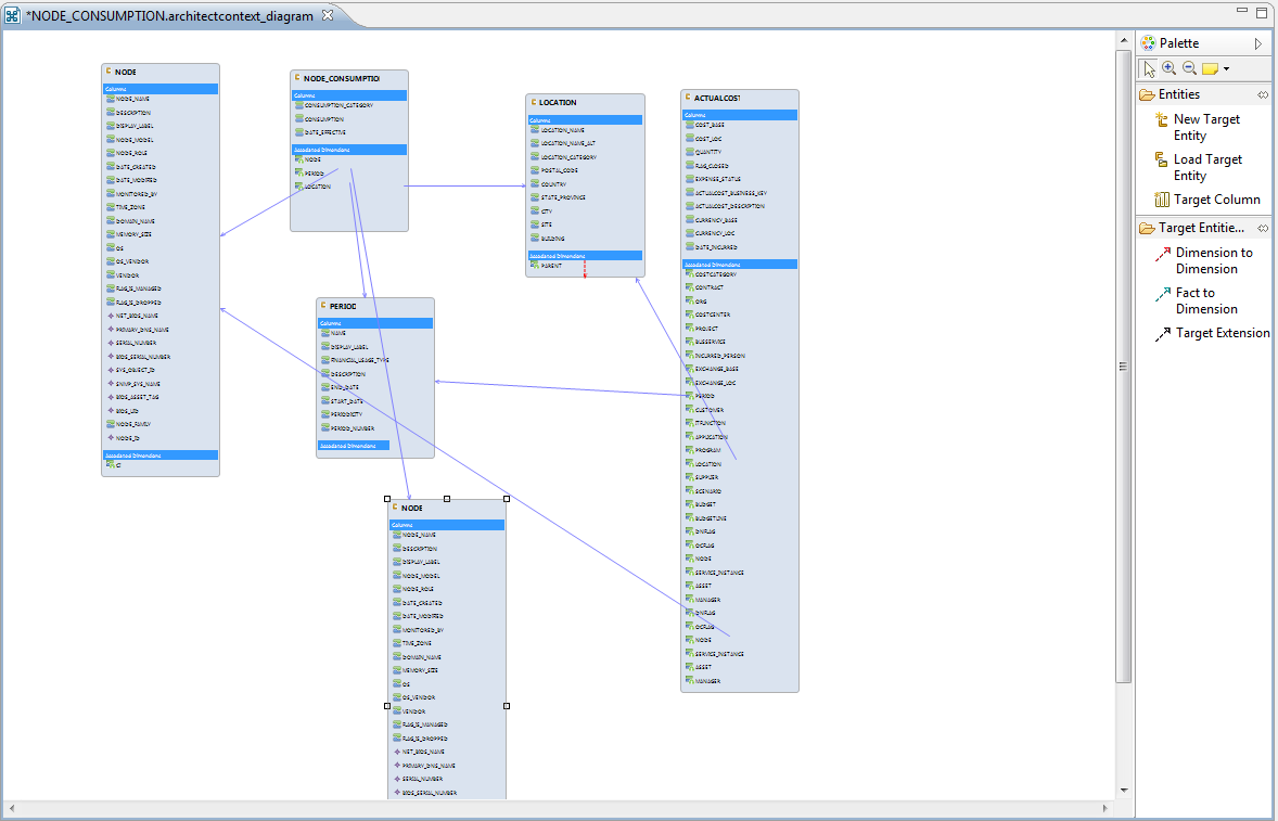
Diagram Editor - Architect Target Designer Tasks
The Architect Target Designer enables you to define a Target entity as well as link associations, or extend an existing entity. Each Target entity in the Architect Target Designer contains columns of fact, or dimension (or both) and associations to other Target entities.
Architect Target Designers can contain one or more Target entities. Usually each Architect Target Designer includes several entities that are related to the same subject (Designer). Target entities can be included in several Architect Target Designers.
The IDE supports the extension of a target entity by creating an association called Target Extension. This enables you to extend an entity by adding to the new entity columns. Adding an extension enables Fact extension and the ability to link a group of Dimensions specifically to the same group. You then use the extension entity to make all associations and links.
The Architect Target Designer is used for modeling the Target data model: the target entities and the links between them.
The Designer refers to the Core CP directory – all the entities modeled in it are created as the xml files in the Core CP directory once the Designer is saved.
The entity is visualized as the table with the fields, it has the properties with entity type selections (fact and\or dimension) and the set of fields attributes based on the entity type.
The designer has the Palette with the available actions:
-
Entities
-
New Target Entity – create a new target entity placeholder on the canvas
-
Load Target Entity – load the existing target entity from the Core CP directory (cp-core)
-
Target Column – add the column to the target entity
-
-
Target Entities Relation
-
Dimension to Dimension – create the intersection point between the dimensions.
-
Fact to Dimension – create the intersection point between fact and dimension.
-
Target Extension – create the reference between the OOTB and the custom entity that is created as the extension.
-
Physically the link between the entities is presented as a FK column in the entity table that refers to the record in the linked dimension table.
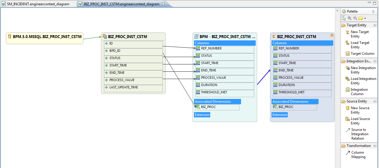
The Engineer Stream Designer allows creating the data path from the source to the target entity.
The Designer works with the selected Source, Integration and Core CP so that the new\existing entities are created\loaded in\from the specific source, integration or core CP directories.
The usual approach is to load the Target Entity that was previously created in the Architect Target Designer and create the new Source\Integration entities and map the fields to the Target entity.
In rare cases when the Target Entity is not supposed to be linked to any other dimension entities, it can be created directly in the Engineer Stream Designer.
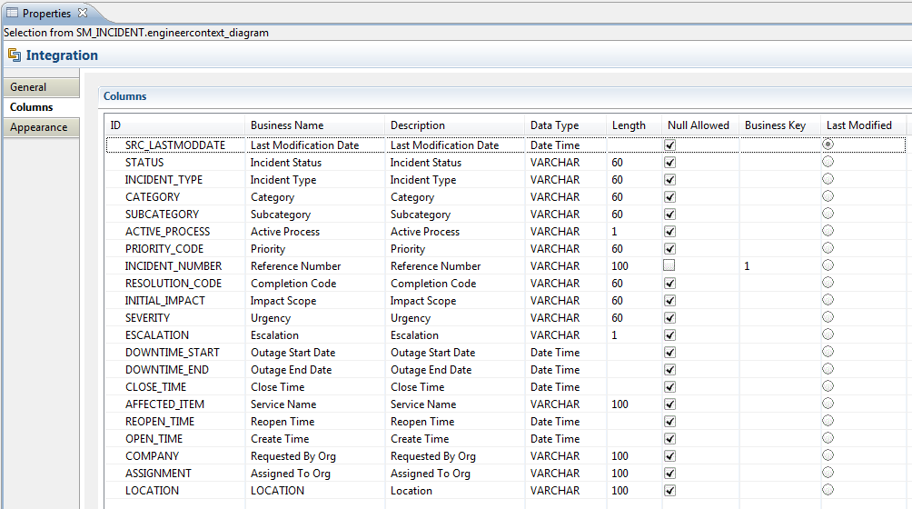
The Integration Entity has the Properties where the columns data types and lengths of the fields should be set as well as the Business Key, Last Modified and nullable columns should be selected.
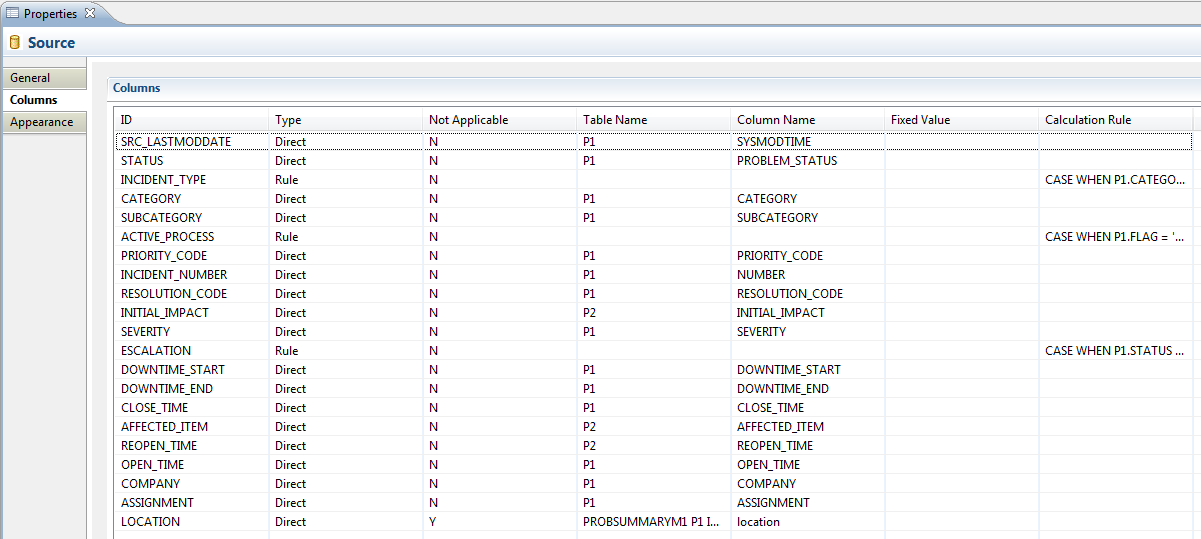
The Source Entity has the Properties that are based on the DB query concept and where the extraction attributes like Table\Join Condition, Where clause and the columns names\aliases and rules can be defined.
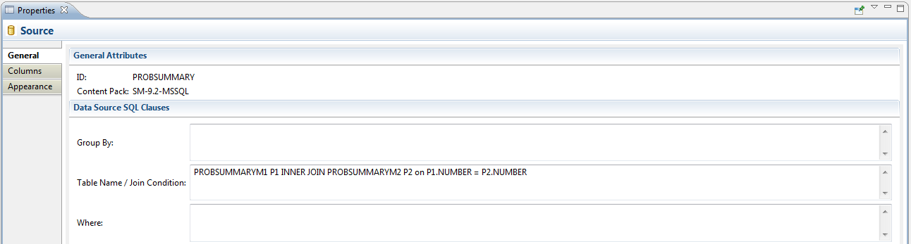
Upon the linkage of the Source Entity to the Integration entity the attributed are populated automatically:
- The Integration Entity name is populated into Table Name field
- The Integration Entity columns are populated into the Columns fields.
Physically the Source Entity is saved as the source entity xml based on which the queries\calls to the data source are built.
The Palette has the set of available actions:
-
Target Entity
-
New Target Entity
-
Load Target Entity
-
Target Column
-
-
Integration Entity
-
New Integration Entity
-
Load Source Entity
-
Integration Column
-
-
Source Entity
-
New Source Entity
-
Load Source Entity
-
Source to Integration Relation (the source entity columns are not modeled by inherited from the Integration entity which the Source entity linked to)
The Integration Entity name is populated into source entity's table Name field and the Integration Entity columns are populated into source entity's Columns fields.
-
-
Transformation
-
Column Mapping – create a direct mapping from the Integration Entity fields to the Target\Transformation Entity fields.
-