


Entity Relationship Diagram utility
The Entity Relationship Diagram utility presents entity relationships for selected files and fields in your database in interactive diagrams (called Entity Relationship Diagrams or ERDs) so that you can have a clear picture of your entity relationships and identify the impact of potential data changes. Additionally, the utility can export the diagrams to static PDF format for offline use.
The utility processes only entity relationships that have a Definition Type of link, erddef, or manual.
- This functionality is available only from the web client.
- To use this utility, you must have the SysAdmin capability word.
- Screen readers are not supported for entity relationship diagrams generated by this utility.
- The accuracy of relationships in the diagrams depends on the correctness of the relevant link and erddef records.
Entity Relationship Diagram interface
The following figure shows the Entity Relationship Diagram interface.
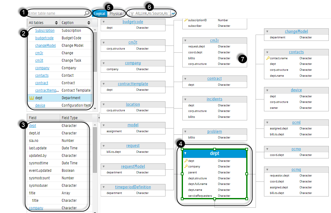
The following table explains different parts of the interface.
| Number | Name | Description |
|---|---|---|
| 1 | Table name input box | Enter the name of a table for which you want to generate an ERD, and then click the magnifying glass icon. For details, see Generate an entity relationship diagram for a file. |
| 2 | Table list | This is a list of tables, including the current table and all its related tables. The current table is identified by a crown icon before its name (for example, dept). |
| 3 | Field or relationship list | Initially, this area lists all fields of the current table. However, if you select a field of the current table in area 4, this area switches to a list of relationship records of the selected field. |
| 4 | Current table and its fields |
In the ERD, the current table is highlighted with a green border. Felds that are the unique key of a table have a key icon before their names. |
| 5 | View tabs |
These two tables allow you to switch the diagram between two views:
By default, the Logical view is displayed. |
| 6 | Filter box |
This box enables you to select filters to further filter information in the diagram.
|
| 7 | Related tables and fields | This area displays all related tables and fields of the current table. |
Dynamic display
When you select another table or field in the diagram, the diagram is reloaded automatically. For details, see View relationships of a specific field in an entity relationship diagram.
Toolbar
The Entity Relationship Diagram interface also provides a toolbar, which allows you to interact with the diagram using the tools on it. For more information, see Interact with an entity relationship diagram.
Related tasks
Generate an entity relationship diagram for a file
View relationships of a specific field in an entity relationship diagram


