


Configure a Path View Map
Configuring a Path View map is useful when you have two or more areas of your network which are separated by undiscovered devices, such as service provider nodes. NNMi enables you to configure a Path View map that traverses undiscovered regions of your network. To configure this kind of Path View map, create a PathConnections.xml file that defines the following:
-
Required. A Start node for each
<CONNECT>to be included in the Path View mapNote The Start node specified must be a Router or Switch-Router device that is managed by NNMi.
- Optional. A unique identifier for a
<CONNECT> - Optional. The outbound interface from each Start node per
<CONNECT> - Required. Any number of undiscovered nodes you want to be included in the map between each
<CONNECT> -
Optional. An End node for a
<CONNECT>to be included in the Path View map.Note The End node specified must be a Router or Switch-Router device that is managed by NNMi.
- Optional. The inbound interface to each End node per
<CONNECT>specified.
Each time NNMi determines a node in the Path View, NNMi checks whether the node is specified as a Start node in the PathConnections.xml file. If the node is specified as a Start node in PathConnections.xml, each <CONNECT> configured in PathConnections.xml is inserted in the Path View map.
Note (NNMi Advanced, plus Route Analytics Management System (RAMS) for MPLS WAN) NNMi can use RAMS data to determine router paths. When RAMS data is used to determine the router paths, NNMi ignores the PathConnections.xml file.
(NNMi Advanced) Path View works only with IPv4 addresses. The NNMi Advanced IPv6 address values are not valid choices for Path View. Any devices in your network that are configured with IPv6 addresses cannot be displayed on Path View maps.
To configure a Path View map:
Using the required format, create a PathConnections.xml file in the following location (see Manage environment variables for more information):
Windows
%NnmDataDir%/shared/nnm/conf/PathConnections.xml
Linux
$NnmDataDir/shared/nnm/conf/PathConnections.xml
The following table describes each of the file elements and its format requirements. (Also see the sample file)
Note Each segment of the path that you specify using the <CONNECT> element is directional. If you want to view the path between two nodes in both directions, make sure you include the Start and End nodes for each direction. You should also include the inbound interface for the Start node. If you do not limit the possible routers by including the inbound interface for the Start node, Path View might find additional routers in the path.
| Element Descriptions |
|---|
|
Required parent element. The file must include only one |
|
Specifies a segment of the path. Each The file can include more than one |
|
Optional. Identifies the connection. NNMi uses the ID value you enter when reporting errors for a If you do not provide an ID value for the path between a Start and End node, any error message for the |
|
Specifies the node where a segment of the path starts. You provide values for the following elements:
|
|
Specifies the node where the
|
|
Required. Designates the end of the XML code that defines one segment of your path view. |
|
Required parent element. Designates the end of the XML code that defines your path view. |
<?xml version="1.0" encoding="UTF-8"?>
<CONNECTIONS>

     <CONNECT>
<ID>
C1 </ID>
<START>
<IP_OR_DNS>StartNode.xx.xxx.x</IP_OR_DNS>
<OUTBOUND_INTERFACE_IFINDEX>3</OUTBOUND_INTERFACE_IFINDEX>
<NEXT_HOPS>
<HOP>hop-1.xxx.xx.xxx</HOP>
<HOP>hop-2.xxx.xx.xxx</HOP>
</NEXT_HOPS>
</START>
<END>
<IP_OR_DNS>EndNode.xxx.xx.xxx</IP_OR_DNS>
<INBOUND_INTERFACE_IFINDEX>6</INBOUND_INTERFACE_IFINDEX>
</END>
</CONNECT>
</CONNECTIONS>
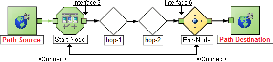
When viewing Path View maps that are configured using the PathConnections.xml file, note the following:
- If the
<END>element is not specified, NNMi connects directly to the Destination node to complete the path. - If the
<END>element is specified, then the associated<IP_OR_DNS>specifies a discovered node as the End node of this segment of your Path View.
Note In this example, the path is the same in both directions. In many cases, the path might be different in each direction.
<?xml version="1.0" encoding="UTF-8"?>
<CONNECTIONS>
<CONNECT>
<ID>
C1
</ID>
          <START>

                <IP_OR_DNS>StartNode.xx.xxx.x</IP_OR_DNS>

             <OUTBOUND_INTERFACE_IFINDEX>6</OUTBOUND_INTERFACE_IFINDEX>

                <NEXT_HOPS>

                     <HOP>hop-1.xxx.xx.xxx</HOP>

                    <HOP>hop-2.xxx.xx.xxx</HOP>

                </NEXT_HOPS>

          </START>

          <END>

                <IP_OR_DNS>EndNode.xxx.xx.xxx</IP_OR_DNS>

                <INBOUND_INTERFACE_IFINDEX>3</INBOUND_INTERFACE_IFINDEX>

          </END>
     </CONNECT>

</CONNECTIONS>
 Swap Nodes button.
