


Monitor with the Network Node Manager iSPI for MPLS Software
The Network Node Manager iSPI for MPLS Software is a smart plug-in that is integrated with NNMi. For enterprises that work on MPLS network, the NNM iSPI for MPLS provides effective and user friendly ways of monitoring MPLS objects and services. After successful integration with NNMi, the NNM iSPI for MPLS is displayed as a separate workspace among the NMMi workspaces. (See, About Workspaces in NNMi Online Help: Using the Console). From this workspace you can access the MPLS Inventory. Each MPLS object has a separate inventory.
The NNM iSPI for MPLS discovers MPLS objects and services like Layer 3 Virtual Private Networks (L3 VPNs), Layer 2 Virtual Private Network (L2 VPNs), Multicast VPNs (MVPNs), PseudoWires (PW), TE Tunnels and Service Distribution Points (SDPs). In addition, discovers Label Switch Paths (LSPs) in MPLS core network. After the discovery, the NNM iSPI for MPLS monitors and generates incidents. The NNM iSPI for MPLS also provides visual representation of all the objects and services, enabling an operator or a network administrator to detect faults quickly and reduce the Mean Time to Repair (MTTR).
The NNM iSPI for MPLS, in conjunction with NNMi, performs the following tasks:
-
Discover and monitor the Layer 3 Virtual Private Network (L3 VPNs) configured on the provider edge devices of the network.
The NNM iSPI for MPLS helps you to monitor an L3 VPN services in MPLS network.
In an MPLS-enabled network, the Provider Edge (PEProvider Edge router. The Internet Service Provider's router that receives your data on the path to your data's final desination. The Customer Edge (CE) router in your network connects to this PE.) routers reside on the perimeter of the service provider’s network. The PE routers communicate with two other kinds of routers; routers inside the MPLS cloud that belong to the service Provider routers (P routers) and Customer Edge (CECustomer Edge router. The router in your network that sends data to an Internet Service Provider's router (the Provider Edge) on the path to the data's final desination.) routers that are located and monitored at customer sites.
Each L3 VPN contains the backbone routers (P routers), the Provider Edge (PE) routers, and the Customer Edge (CE) routers.
The NNM iSPI for MPLS helps you to perform the following tasks:
Monitor L3 VPNs and VRFs
You can discover the Virtual Routing and Forwarding (VRF) tables and Route Targets (RTs) participating to form an Layer 3 VPN on the network. A VPN is formed by the set of VRFs on a Provider Edge router (PE). You can monitor and view the real-time status of the complex L3 VPNs. You can navigate to L3 VPN forms to view the attributes and incidents-related to that VPN. In addition, you can navigate to the PE node form to troubleshoot the network connectivity. For more information, see Node Form: L3 VPN PE Interfaces Tab.
Manage Faults
You can detect the changes in the L3 VPN network such as the status of the VRF changing from Up to Down by using the NNM iSPI for MPLS views. The NNM iSPI for MPLS provides a quick way to view the enriched incidents that help you understand and resolve a problem in your network. For more information, see MPLS Incidents.
For more information about the L3 VPN, VRFs, Route Targets, and Shadow Routers, see L3 VPN, VRF, Route Targets, VRF-Lite, and Shadow Routers.
-
Discover third-party Inter-Provider MPLS clouds, and discovering and monitoring Customer Edge (CE) routers at customer sites
Overview of Inter-Provider VPN
The NNM iSPI for MPLS supports Inter-provider VPN technology.
Inter-provider technology allows data transmission between MPLS VPN providers and CE routers residing in remote MPLS client sites by using a third-party VPN provider. PEs residing within the MPLS VPN provider, function as Area Border RoutersArea Border Routers connect the main backbone network to one or more areas. (ABRs). The LSP paths of these ABRs interconnect with the third-party MPLS network cloud through IP forwarding. The third party MPLS network cloud is called a carrier cloud. This carrier cloud is identified by a unique Autonomous System NumberAutonomous System Numbers are IP routing prefixes designated by the Internet Assigned Numbers Authority (IANA). (AS#) assigned to it.
The NNM iSPI for MPLS supports Back-to-Back VRF methodology.
Back-to-Back VRF is one of the common implementations of the Inter-Provider VPN technology. A back to back VRF setup can have multiple carrier service provider networks (carrier clouds), each assigned with a unique AS#. PE routers residing within a carrier service provider network function as Autonomous System Boundary RoutersAn autonomous system boundary router is used to establish routes with external autonomous systems and carry out data transmission using Border Gateway Protocol (BGP) (ASBRs).
The NNM iSPI for MPLS discovers CE nodes that are located outside the MPLS VPN Network. The NNM iSPI for MPLS detects and manages all the nodes participating in the back-to-back VRF setup. You can monitor the connectivity between the PE node residing in the MPLS VPN Network, the IP addresses and AS#s of carrier service provider network, and geographically dispersed CE nodes residing within the client sites. The NNM iSPI for MPLS helps you view:
- PE-CE connectivity
- Name and AS# of the carrier service provider networks
- Next Hop IP
- Next Hop AS
- AS Path
-
Discover and monitor the Virtual Private LAN Service VPNs (VPLS VPNs) on the network
Overview of the MPLS L2 VPN
The NNM iSPI for MPLS helps you to monitor the L2 VPNs (VPLS VPN and VPWS VPN) on your network.
Virtual Private LAN Service (VPLS VPN)
A VPLS VPN is formed by PseudoWire VCs with the same VPN ID. In a VPLS VPN or a Layer 2 VPN, multiple sites communicate using Ethernet-based multipoint to multipoint communication over a Packet Switched Network (PSN). The PE routers use Border Gateway Protocol (BGP) and Label Distribution Protocol (LDP) to communicate within the VPLS VPNs.
Virtual Private Wire Service VPN (VPWS VPN)
A VPWS VPN is formed by VC LSPs with the same VPN ID. In a VPWS VPN or Layer 2 VPN, point-to-point link connects the CE devices through a Packet Switched Network (PSN) using PseudoWires VCs. Configure the VPWS VPNs from the MPLS Configuration workspace.
Virtual Private Wire Service VPN (VPWS VPN)
In a VPWS VPN or Layer 2 VPN, point-to-point link connects the CE devices through a Packet Switched Network (PSN) using PseudoWires VCs. You can change the configuration for the VPWS VPNs from the MPLS Configuration workspace.
The NNM iSPI for MPLS helps you perform the following tasks:
Monitor PseudoWire VCs
You can discover the PseudoWire VCs participating to form an L2 VPN. You can monitor and view the status of the L2 VPNs. You can navigate to L2 VPN forms to view the attributes and incidents-related to that L2 VPN.
In addition, you can monitor Attachment circuits (ACs), Virtual forwarding Interfaces (VFIs) for VPLS VPN and VPWS VPN. These VFIs are named as L2VPNName@NodeName and GroupName@NodeName respectively.
You can discover the PseudoWire VCs participating to form an L2 VPN. You can monitor and view the real-time status of the L2 VPNs. You can navigate to L2 VPN forms to view the attributes and incidents-related to the network.
In addition, you can monitor Attachment circuits (ACs), Virtual forwarding Interfaces (VFIs) for VPLS VPN and VPWS VPN. These VFIs must be named as L2VPNName@NodeName and GroupName@NodeName respectively.
Manage Faults
You can detect the changes in the topology such as PseudoWire VC is Down or Up by using the NNM iSPI for MPLS views. In addition, the NNM iSPI for MPLS generates enriched incidents that help you understand and resolve a problem in your network. For more information, see MPLS Incidents.
L2 VPN Renaming
The NNM iSPI for MPLS assigns a meaningful VPLS VPN name to each discovered VPLS by appending the VPLS name with unique VPN ID. For example, VPLS_VPN ID.
To configure the VPWS, type the VPWS name from the MPLS Configuration workspace. If any PseudoWire VC is not participating to form a VPLS or a VPWS, it appears under the Default Group.
 To update the VPLS VPN name:
(In the VPLS VPN Form, type the new name. Click
 (the Save and Close button). The new name appears in the VPLS VPN inventory.)To update the VPWS VPN name:
(From the VPWS VPN Form, type the new name. Click
(the Save and Close button). The new name appears in the VPWS VPN inventory.) -
Discover and monitor the Virtual Private Wire Service VPNs (VPWS VPNs) in the network
Overview of the MPLS L2 VPN
The NNM iSPI for MPLS helps you to monitor the L2 VPNs (VPLS VPN and VPWS VPN) on your network.
Virtual Private LAN Service (VPLS VPN)
A VPLS VPN is formed by PseudoWire VCs with the same VPN ID. In a VPLS VPN or a Layer 2 VPN, multiple sites communicate using Ethernet-based multipoint to multipoint communication over a Packet Switched Network (PSN). The PE routers use Border Gateway Protocol (BGP) and Label Distribution Protocol (LDP) to communicate within the VPLS VPNs.
Virtual Private Wire Service VPN (VPWS VPN)
A VPWS VPN is formed by VC LSPs with the same VPN ID. In a VPWS VPN or Layer 2 VPN, point-to-point link connects the CE devices through a Packet Switched Network (PSN) using PseudoWires VCs. Configure the VPWS VPNs from the MPLS Configuration workspace.
Virtual Private Wire Service VPN (VPWS VPN)
In a VPWS VPN or Layer 2 VPN, point-to-point link connects the CE devices through a Packet Switched Network (PSN) using PseudoWires VCs. You can change the configuration for the VPWS VPNs from the MPLS Configuration workspace.
The NNM iSPI for MPLS helps you perform the following tasks:
Monitor PseudoWire VCs
You can discover the PseudoWire VCs participating to form an L2 VPN. You can monitor and view the status of the L2 VPNs. You can navigate to L2 VPN forms to view the attributes and incidents-related to that L2 VPN.
In addition, you can monitor Attachment circuits (ACs), Virtual forwarding Interfaces (VFIs) for VPLS VPN and VPWS VPN. These VFIs are named as L2VPNName@NodeName and GroupName@NodeName respectively.
You can discover the PseudoWire VCs participating to form an L2 VPN. You can monitor and view the real-time status of the L2 VPNs. You can navigate to L2 VPN forms to view the attributes and incidents-related to the network.
In addition, you can monitor Attachment circuits (ACs), Virtual forwarding Interfaces (VFIs) for VPLS VPN and VPWS VPN. These VFIs must be named as L2VPNName@NodeName and GroupName@NodeName respectively.
Manage Faults
You can detect the changes in the topology such as PseudoWire VC is Down or Up by using the NNM iSPI for MPLS views. In addition, the NNM iSPI for MPLS generates enriched incidents that help you understand and resolve a problem in your network. For more information, see MPLS Incidents.
L2 VPN Renaming
The NNM iSPI for MPLS assigns a meaningful VPLS VPN name to each discovered VPLS by appending the VPLS name with unique VPN ID. For example, VPLS_VPN ID.
To configure the VPWS, type the VPWS name from the MPLS Configuration workspace. If any PseudoWire VC is not participating to form a VPLS or a VPWS, it appears under the Default Group.
To update the VPLS VPN name:
(In the VPLS VPN Form, type the new name. Click
(the Save and Close button). The new name appears in the VPLS VPN inventory.)To update the VPWS VPN name:
(From the VPWS VPN Form, type the new name. Click
(the Save and Close button). The new name appears in the VPWS VPN inventory.) -
Discover and monitor the TE tunnels on the network
Overview of the MPLS TE Tunnels
In MPLS network, you can setup Traffic Engineering tunnels for better quality of service between desired source and destination
MPLS Traffic Engineering (MPLS TE) is the process of selecting and reserving the path between the nodes to optimize network resources for better bandwidth utilization and ensure better Quality of Service (QoS). Traffic Engineering (TE) is essential for service provider backbones. Usually, the shortest path is chosen for data transfer
In an MPLS Traffic Engineering network, the routers can communicate by using TE tunnels. The TE Tunnels are one of the mediums through which you can manage the data transmission from a source to a destination as well as maintain a quality of service.
MPLS Traffic Engineering (MPLS TE) is the process of selecting and reserving the path between the nodes to optimize network resources for better bandwidth utilization and ensure better Quality of Service (QoS). Traffic Engineering (TE) is essential for service provider backbones. The network administrator configures the TE Tunnels to ensure the desired bandwidth usage and to provide better quality of service. Usually the shortest path is chosen for data transfer but TE tunnels allow traffic to be routed through a specific path (tunnel) thus, maintaining the required quality of service and bandwidth.
The NNM iSPI for MPLS discovers the TE tunnels in the MPLS core and provides a TE Tunnel Inventory with all the TE Tunnels discovered, along with their status. In addition, you can find the faults in MPLS traffic engineering tunnels. Check Incidents and Status tabs.
The NNM iSPI for MPLS helps you to perform the following tasks:
Monitor TE Tunnels
You can monitor using TE Tunnel inventory which lists all the discovered TE Tunnels with their status. Any change in TE tunnel would be indicated by the status on inventory. For further details on a particular TE Tunnel, you can open TE Tunnel form from the inventory to view the attributes and incidents related to the network. This helps in isolating a fault quickly and reduces the Mean Time To Repair (MTTR).
Manage Faults
You can detect the changes in the topology such as the status of the TE Tunnel changing from Up to Down or when it is Rerouted. The NNM iSPI for MPLS provides generates enriched incidents that help you understand and resolve a problem in your network. For more information, see MPLS Incidents.
-
Discover and monitor the PseudoWire VCs on the network.
Overview of the MPLS PseudoWire VC
A PseudoWire VC is a point-to-point link for data transmission between the two nodes using any L2 technology. There are two types of L2 VPNs - Virtual Private Wire Service (VPWS)A Virtual Private Wire Service VPWS is a point-to-point link through a packet switched network connecting two Customer Edge devices.and Virtual Private LAN Service (VPLS)A VPLS connects several LAN segments over a packet switched network (PSN).. In PseudoWire VC, the transmission of data is bi-directional. For example, if there are two endpoints A and B, data transmission is from A to B and B to A. A bidirectional PseudoWire VC consists of a pair of unidirectional VC LSPs, one in each direction. The unique VC ID in between two endpoints identifies the LSPs. To discover the complete Pseudowire VCs, make sure to discover both the endpoints (VC LSPs) of the PseudoWire VC.
You can discover and monitor the PseudoWires VCs on the network. The NNM iSPI for MPLS helps you perform the following tasks:
Monitor PseudoWIre VC
You can monitor the PseudoWires VC participating on the network from the Pseudo Wire VC inventory. You can navigate to PseudoWires VC forms to view the attributes and incidents-related to that particular PseudoWire VC.
Manage Faults
The NNM iSPI for MPLS identifies the changes in the topology such as the status of the PseudoWire VC is Down. The NNM iSPI for MPLS generates incidents that help you understand and resolve to a problem in your network. For more information, see MPLS Incidents.
-
Discover and monitor Label Switch Paths (LSPs)
Overview of the Label Switch Path
Label Switch Paths (LSPs) play the most important role in data transfer within an MPLS network. LSPs are set up by Label Distribution Protocol (LDP) to trace a path from a source to destination device within an MPLS network. These source and destination devices are known as Label Switch Routers (LSRs) or Provider Edge (PE) routers. An LSP path originates from an LER and based on the prefixed label, transfers the data to the intermediate router in the path. The intermediate routers are also known as Provider Routers (P Routers). When a P Router receives a data packet, it swaps the prefix label and pushes the data forward to the next P Router. This process continues till the data reaches the destination LER. The destination LER then drops the label.
The NNM iSPI for MPLS services utilize LSPs and therefore, any impact on LSP has a direct effect on these services. The NNM iSPI for MPLS has introduced Service Mapping. Service Mapping is where, an LSP path can be traced between various services residing on two different MPLS-enabled nodes. Using the NNM iSPI for MPLS, you can discover LSPs in MPLS core network and monitor MPLS services for to determine any service impact because of LSP related issue.
Example of a Label Switch Path
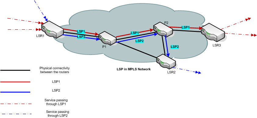
In the example above, there are two LSPs passing through an MPLS cloud. The first one connects the the Edge Routers LER1 and LER3 by passing through P Routers (P1 and P2). The second originates from edge router LER1 and passes through the P Routers P1 and P2, and ends at Edge Router LER2. In this example, LSP1 is mapped to two services and LSP2 is mapped to one service.
LSP Service Mapping
In addition to discovering the LSPs in core MPLS network, iSPI for MPLS also maps these LSPs to respective layer 3 and layer 2 services. This LSP service mapping is useful to detect impacts on these services caused because of faults in the core (corresponding LSP).
Prerequisite to Enable LSP Mapping:
LSP service mapping is available for services configured on LSRs for which, SSHv2 credentials are provided in iSPI for MPLS Configuration under Configuration workspace. For more information on how to configure devices see, Configure Device Credentials.
-
Discover and monitor the Provider Edge (PE) - Customer Edge (CE) relationship on the network. Monitor the Customer Edge nodes and finding the service-related impact analysis
Overview of the MPLS Customer Edge (CE) Management
You can monitor the logical link connectivity between the PE node and CE node in an L3 VPN topology. The NNM iSPI for MPLS helps you monitor the following:
- One PE interface connected to one CE interface on the network.
- One PE interface connected to multiple CE interfaces on the network. This PE-CE links are connected by using a hub on the network.
- Multiple PE interfaces connected to one CE interface on node on the network. This PE-CE link connectivity is using the Hot Standby Routing Protocol (HSRP) or equivalent.
- Multiple PE interfaces connected to multiple CE interfaces on the network.
For example, NNMi monitors the CE1 and CE2 nodes and interfaces on the nodes. The NNM iSPI for MPLS helps you monitor the PE-CE communication links. In addition, the NNM iSPI for MPLS helps you monitor two CE interfaces on the CE node communicating with one PE interface and two PE interfaces communicating with one CE interface. The NNM iSPI for MPLS does not monitor the PE3- CE3 link connectivity as the CE3 node is not available in NNMi topology.
You can check the status of the PE interface, CE interface, and the PE-CE connectivity from the MPLS views. View the PE-CE information in the CE Interface tab, PE Interface tab, and L3 VPN tab of the node form. For more information, see Node Form: L3 VPN PE interfaces.
The discovery of CE nodes participating in an L3 VPN may require multiple rounds of discovery, even if both the CE node and the corresponding PE node are seeded at the same time. The actual number of discovery cycles (one or two) depends on manageability of CE node and also, the sequence in which the PE and CE nodes are discovered by NNMi and the NNM iSPI for MPLS.
The NNM iSPI for MPLS supports the duplicate IP address for the PE-CE link connectivity. For more information, see Duplicate IP address Support with the NNM iSPI for MPLS.
The NNM iSPI for MPLS uses NNMi capabilities to monitor and manage the CE interface. NNMi polls the CE interface on the CE node and generates incidents whenever the status of the CE interface is down. The NNM iSPI for MPLS listens to the incident and updates the status of the CE interface in the MPLS views.
To use the CE management feature, use NNMi Configuration workspace to configure the CE interfaces in the interface group. You should add the interface groups with MPLS capabilities that help in monitoring the PE- CE logical link connectivity.
To add or edit an interface group to include the MPLS PE and CE capabilities from NNMi Configuration workspace- From the workspace navigation panel, select the Configuration workspace.
- Select Interfaces Groups ->Interface Settings tab.
- Do one of the following:
- To create an Interface Settings definition, click
 (the New icon).
 - To edit an Interface Settings definition, select a row, click
 (the Open icon).
 - In the Interface Group form, select the Additional Filters tab.
- Add the following MPLS capability to monitor the PE interfaces
capability = com.hp.mpls.capability.iface.l3vpnpeiface. - Add the following MPLS capability to monitor the CE interfaces
capability = com.hp.mpls.capability.iface.l3vpnceiface.
- Add the following MPLS capability to monitor the PE interfaces
- Click
 (the Save and Closeicon).
To enable polling for the CE interfaces, check the Global Control group box from the Monitoring Configuration workspace. For more information, see NNMi Help for Administrator, Using the Monitoring Configuration form.
- Monitoring the MPLS Inventory from the Global Network Manager and Regional Manager.
- Visual representation of MPLS services and convenient troubleshooting of problems using graphical views provided by the NNM iSPI for MPLS.
- Investigating the problems of the network by viewing the incidents and service impact incidents.
- Configuring devices for non-SNMP framework support.
- Investigating incoming and outgoing traffic within an MPLS network by generating reports. This is only possible after you integrate the NNM iSPI for MPLS with NNM iSPI Performance for Metrics.
- Discovering and monitoring the Multicast VPNs (MVPNs) on the network by using the NNM iSPI for IP Multicast capabilities.This is only possible after you integrate theNNM iSPI for MPLS with NNM iSPI for IP Multicast
- Monitoring and troubleshooting an L3 VPN by using Route Analytics Management Software (RAMS) capabilities.This is only possible after you integrate the NNM iSPI for MPLS with RAMS.
- Setting up the MPLS related probes by using the NNM iSPI Performance for Quality Assurance (QA) capabilities.By integrating with the NNM iSPI performance for QA you can manage end-to-end services on the MPLS nodes .
You can monitor your MPLS network by:
- Accessing form view of each MPLS object
- A form view provides detailed information about MPLS objects.
- Different tabs under each form make it easier for you to view specific data .
- You can perform following tasks from the form views:
- Access analysis pane (see, About Analysis Pane in NNM Online Help: Using the console).
- Launch topology view, using Actions (see, Actions Available in NNM iSPI for MPLS in NNM iSPI for MPLS Online Help).
- View incidents from the incidents tab.
- Launching Topology Map views for layer 3 and layer 2 topologies.
A topology map view provides a visual representation of the MPLS network. You can launch a layer 3 or a layer 2 topology map to view the connectivity and status of each MPLS object or a service in the MPLS network.
- Viewing incidents generated for MPLS objects
The NNM iSPI for MPLS actively notifies you when an important event occurs by generating incidents. You can troubleshoot your MPLS network based on incidents generated for MPLS objects and services.
The NNM iSPI for MPLS supports the following environments/frameworks:
Multi Tenant Architecture
Overview of Multitenant Architecture
The NNM iSPI for MPLS, in conjunction with Network Node Manager supports Multitenant architecture. You can create Tenants or partition your network across multiple users. A tenant can also be defined as a security group to which a node or an MPLS object belongs. As an administrator, you can restrict operators to view and control a set of nodes and MPLS objects, if they do not belong to the same security group as that of this set.
As a tenant, a user can view all the nodes and MPLS objects participating in a network in the map view. However, the inventory and the form views will display only those objects that the user has permission to access. For example, if a user has access to three nodes out of five in a network, the map view will show the five nodes,however the other two nodes are not 'clickable' and no information is available for those two nodes. Moreover, the inventory and form view will list only three accessible nodes.
Following is the list of the NNM iSPI for MPLS objects supporting multitenant architecture:
- TE Tunnel Inventory: A user can monitor only those tunnels that are associated with the nodes in the user's security group
- VRF Inventory in VPN: A user can monitor only those VRFs that are associated with the nodes in the user's security group
- VRF neighbors in VRF: A user can monitor only those VRFs that are associated with the nodes in the user's security group
- VPN Inventory: A user can monitor a VPN, if at least one VRF participating in that VPN belongs the user's security group
- PseudoWire Inventory: A user can monitor only those PseudoWire virtual circuits (VCs) that are associated with the nodes in the user's security group
- VPLS Inventory: A user can monitor a VPLS if at least one PsuedoWire VC participating in that VPLS are associated with the nodes in the user's security group
- VPWS Inventory: A user can monitor a VPWS if at least one PsuedoWire VC participating in that VPWS are associated with the nodes in the user's security group
- Maps: For L3 VPN, L2 VPN, LSP, TE Tunnel path, a user can view all the nodes participating in the VPN or TE tunnel but can monitor only those nodes that belong to the user's security group
Security group is also applicable to incidents, MPLS related probes (applicable only if, the NNM iSPI for MPLS is integrated with NNM iSPI Performance for QA), and reports. This means, a user can view incidents for accessible objects, probes for accessible VRFs, and reports for accessible nodes alone.
Multi tenancy can be configured in NNMi workspace through Configuration -> Security. For more details, see Online Help for NNMi.
- Overlapping Address Domain
The NNM iSPI for MPLS supports the following device types:
- Cisco routers
- Cisco IOS-XR routers
- Juniper( M/T/J ) series routers
- Ericsson Redback
- Alcatel 7750 and 7710 series routers
- Huawei
For information about the supported combinations of devices for the NNM iSPI for MPLS objects and services, see NNM iSPI for MPLS 10.00 Support Matrix document.
After you install (and configure) the NNM iSPI for MPLS on the NNMi management server, you can monitor and troubleshoot the problems in your network with the additional table and map views provided by the NNM iSPI for MPLS.