


Administer the NNM iSPI for IP Telephony
As an administrator, you can configure the NNM iSPI for IP Telephony according to your monitoring requirements for the IP telephony devices and services on the network. This topic includes the following sections:
- Discover IP Telephony Networks
- Extract a Host Key
- Global IP Telephony Network Management
- Manage the Lifecycle of NNMi Nodes Hosting IP Telephony Devices
- Delete IP Telephony Entities from the NNM iSPI for IP Telephony
- Configure Processing of Traps Sent by Nortel Call Server
- Log and Trace
- Integration with ClarusIPC
You can gain access to the configuration forms presented by the NNM iSPI for IP Telephony, which help you to change the following settings:
- Exclude IP Phones that you do not want to monitor for Cisco and Avaya
- Interval for various NNM iSPI for IP Telephony monitoring tasks
- QOS and MOS monitoring threshold configuration
- Reporting configuration
- Data access configuration
- Regional Manager configuration
recommends that you configure the settings listed above before you seed any IP Telephony nodes in NNMi and start to monitor these nodes using the NNM iSPI for IP Telephony. However, you can use the configuration forms to configure the settings or modify the existing settings even after seeding the IP Telephony nodes or when the NNM iSPI for IP Telephony is operational.
To launch the IP Telephony Configuration forms:
- From the Workspaces navigation pane, click Configuration > iSPI for IP Telephony Configuration. The NNM iSPI for IP Telephony window appears.
Quick Start Configuration Wizard
You can also run the NNM iSPI for IP Telephony Quick Start Configuration Wizard to configure the settings to manage your network environment. recommends that you use the NNM iSPI for IP Telephony Quick Start Configuration Wizard for the initial configuration setup.
To access the quick start wizard, type the following URL in your browser:
http://<fqdn>:<port>/iptquickstart/wizard
<fqdn>: The fully qualified domain name of the NNMi management server
<port>: The HTTP port number used by the NNM iSPI for IP Telephony. The default port number is 10080.
By default, the NNM iSPI for IP Telephony Quick Start Wizard is configured to use the credential-based authentication. However, you can configure the Quick Start Wizard to use the PKI-based authentication.
Configure Quick Start Wizard to use PKI-based authentication
To configure theNNM iSPI for IP Telephony Quick Start Wizard to use the PKI-based authentication:
- Log on to the NNM iSPI for IP Telephony server.
- Navigate to the following directory:
On Windows
%nnmdatadir%\nmsas\ipt\confOn Linux
/var/opt/OV/nmsas/ipt/conf - Open the
nms-auth-config.xmlfile with a text editor. - Locate the following lines of code:
<realm name="console"><mode>X509</mode></realm> - Add the following lines of code after the above code:
<realm name="iptqswrealm"><mode>X509</mode></realm> - Save and close the file.
- Run the following command at the command prompt:
On Windows
%nnminstalldir%\bin\nmsiptauthconfigreload.ovplOn UNIX/Linux
/opt/OV/bin/nmsiptauthconfigreload.ovpl
Clarus IPC
As an administrator you can enable or disable integration of the NNM iSPI for IP Telephony with Clarus IPC to view the Clarus IPC generated traps that convey alerts for the Cisco IP Telephony service test results and configuration changes. The integration with Clarus IPC also allows you to launch the Remote Hand and Help Desk applications from Clarus IPC for certain Cisco IP Phones from the NNM iSPI for IP Telephony IP Phone view for Cisco IP phones.
Discover IP Telephony Networks
You can start monitoring all the IP telephony infrastructure after a cycle of polling by the NNM iSPI for IP Telephony. You can install the NNM iSPI for IP Telephony for an IP telephony network that is already being managed by NNMi, or you can configure NNMi to monitor an IP telephony network after the installation of the NNM iSPI for IP Telephony.
If you install the NNM iSPI for IP Telephony on an NNMi management server that is already managing an IP telephony network, the subsequent NNMi discovery prompts the NNM iSPI for IP Telephony to discover the IP telephony devices and topologies. Completion of the NNMi discovery cycle always triggers the discovery of the IP telephony network by the NNM iSPI for IP Telephony. By default, the NNMi and NNM iSPI for IP Telephony discovery schedule is set to 24 hours.
After installing the NNM iSPI for IP Telephony to monitor an IP telephony network that was already being managed by NNMi, you can wait for the next discovery cycle of NNMi, or you can run the Configuration Poll action to discover the IP telephony network immediately.
If you install the NNM iSPI for IP Telephony to monitor a network, which is not already managed by NNMi, you must seed all the IP telephony devices from the NNMi console after installation. Seeding enables NNMi to perform Configuration Poll and triggers a cycle of discovery. In effect, the IP telephony network is discovered at the end of the discovery cycle.
Discover IP phones
As IP phones are not SNMP-enabled devices, a standard discovery by the NNM iSPI for IP Telephony cannot discover these phones. To discover IP phones available in your network, you must:
- Seed the access switches to which the IP phones are connected
- Set up auto-discovery rules for IP phones
- Disable ping sweep while setting up auto-discovery for IP phones
The auto-discovery rule discovers the IP telephony network including layer 2 connections between IP phones on the network.
Extract a Host Key
To extract an RSA level 2 host key for Avaya Communication Manager (CM), Cisco Unified Communications Manager (CUCM), and Acme Session Director (SD):
- On Linux
-
Make sure that no trusted host key is stored for the CM, CUCM, or SD in the Linux client machine at the following location:
{home-dir}/.ssh/known_hostsTo make sure of this:
-
See the host keys present in the system by running the following commands:
vi {home-dir}.ssh/known_hostscat {home-dir}.ssh/known_hostsThe machine displays the list of host keys present in it.
A few examples of the host keys
nnmilxx ssh-rsa
AAAAB3NzaC1yc2EAAAABIwAAAQEA0QRT72TDI2FJ+VrVpNU8zTcdbz3gCyH2UFjqdU7Re9zT
Eq252Kzrrdriyvnaxhx4xcIHC+6iKjfF6UrEXAITon3mf1Ginp7AlBIpL6lgdkcKgH3VzjWtIkx1dC0BEZa
HPseVP7PWy4RuSyyPbleql3O/Xltlm8MQPPYl3ZDeeQR07lxAU43685KK1w==
localhost ssh-rsa
AAAAB3NzaC1yc2EAAAABIwAAAQEA0QRT72TDI2FJ+VrVpNU8zTcdbz3gCyH2UFjqdU7Re9zTl
MuJf11RS4lyi0lXgZO4Yn7JsmT8BBDE11+zefB+si5vXTonpGfC/eOJr4HlM+73fdqVX1Br0tITxpoz3t
seVP7PWy4RuSyyPbleql3O/Xltlm8MQPPYl3ZDeeQR07lxAU43685KK1w==
192.168.15.14 ssh-rsa
AAAAB3NzaC1yc2EAAAABIwAAAIEArARKap4fSZLG0xkqT57TiftD34TCCrh5oIS6CQ6qfBmk0uw
ANRx11g1mWppdNqIpT2+tHpn+sNN11JGV9IlnmxBnkdpyJFFNZwOK9dbB0glLY/ARuZOjJyb7y5Jd
X0TYY+Sv6C9lcMzFLV8e5OBKJyxWSelQhvjJQTRzKPOKN+s=
192.168.16.17 ssh-rsa
AAAAB3NzaC1yc2EAAAABIwAAAQEArC1tF99fLtDQxAPoG+JLGnT10WWEtInB2w4SL3+Om6je9
iqBp0eL030O4hBs/et6ElZbKTo0kTbnXoopqiSKSrKtnjkxFcuXicOSxOFRPSqLin6BnLVsNguBU0ue
deYr8kOQDa/nGNwwp2lSqHTlHyzk1XiaLAglVg1yV92GISsgc36UAYomhGyF9piXPiQ==
nnmiwinxx,192.168.17.18 ssh-rsa
AAAAB3NzaC1yc2EAAAABIwAAAQEAu0Mi73QSqJrZ2jO5LPPwFZH+nECEfD3mEg0e5AEn8Jw68
zFiVtbmAXc0wshTeuW4dfo9OYKtqTxjWacye+ZgX7KvjSn9SATukQG1lp55bFhkSAuB46Y5OjqKpD+
8ud5FpipzbuUklqtzYAkzgD9bW+Z6pEBx2cA+lFV1NwQEuKUZCqhLFsbRsdvrJrw==
nnmiwinxx,192.168.19.21 ssh-rsa
AAAAB3NzaC1yc2EAAAABIwAAAQEA2YE67SaAeym4y73RW8Vc7bx3jnjRb4RqsqGr5YnI3cpf425D
Jv28ew4t+P7Bz+K78pFzbcaQtcwJZsNYc+MNVMXU39eS3b0fWDI0YlvexiUFAWlgH5bWiBioGt2STdp
2WybstDHDfAS4VhBQLlMwe/pBY5Uj+pL0hXtds33abVR2bALD/96E2SQ==
iptnnmwinx,192.168.24.14 ssh-rsa
AAAAB3NzaC1yc2EAAAABIwAAAQEA0TdH+dc7OAUjehjTD6iwHshfGWUyydlA9BSyD9q4hZZOSYU
VotByDGLONCfdhKqituAXEeXSbVxETingG1Kgzyu7UdO5T63xRwA3FtbJJbh1HK//p6hsk+cXhQ32uB
+eGy6GnrJM543Yz0bIz7ipSm+DjqkhlNYtTV0wmmli3PozAW2sS8LOuo6LPQ==
-
Delete the entry that corresponds to the IP address of the CM, CUCM, or SD. For example, if the IP address of your CM, CUCM, or SD is 192.168.16.17, the host key that corresponds to the CM, CUCM, or SD may look like this:
192.168.16.17 ssh-rsa AAAAB3NzaC1yc2EAAAABIwAAAQEArC1tF99fLtDQxAPoG+JLGnT10WWEtInB2w4SL3+Om6je9deYr8kOQDa/nGNwwp2lSqHTlHyzk1XiaLAglVg1yV92GISsgc36UAYomhGyF9piXPiQ==
-
-
Run an
sshcommand to the IP address of the remote CM, CUCM, or SD as follows:ssh 192.168.16.17
The machine displays the following messages:
The authenticity of host '192.168.16.17 (192.168.16.17)' can not be established.
RSA key fingerprint is ba:40:95:5f:8c:ea:fb:ad:b5:97:5a:4e:d0:85:50.
Are you sure you want to continue connecting (yes/no)?
-
Note down the RSA key fingerprint as follows:
ba:40:95:5f:8c:ea:fb:ad:b5:97:5a:4e:d0:85:50You can provide this RSA key in the Host Key field of the SSH configuration UI of the NNMi.
- On Windows
If you do not have a Linux client machine to extract the host key, you can extract a host key from a Windows machine using the PuTTY application or any other similar application.
To extract an RSA level 2 host key for the CM, CUCM, or SD using the PuTTY application:
-
Open the PuTTY application and type the host name or IP address of the CM, CUCM, or SD under the Host Name (or IP address) field .
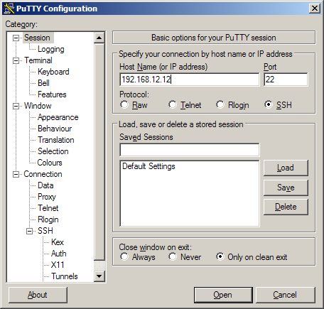
-
Select SSH under the Protocol field.
- Select Only on clean exit under the Close window on exit: field.
-
Click Open. A pop-up window opens:
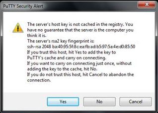
Note down the rsa2 key fingerprint and use it in the NNMi.
If the pop-up window does not open, it indicates that the host key for the IP address of the CM, CUCM, or SD is already cached in the registry by PuTTY in a previous session. In this scenario, you must clear the registry entry and repeat step 1 to step 4.
To clear the registry entry:
-
Browse the following directory:
USER\Software\SimonTatham\PuTTY\SshHostKeys
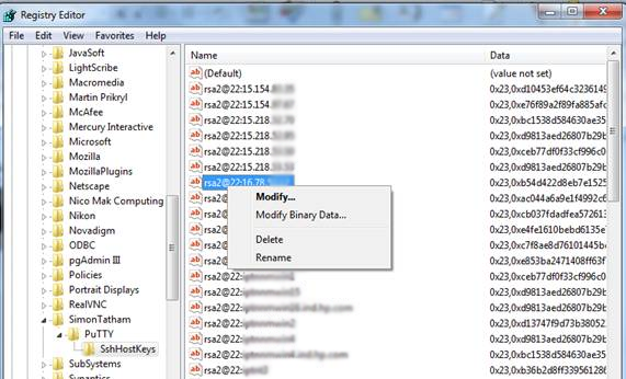
- Select and right-click the host key that corresponds to the IP address of the physical CM,CUCM, or SD.
- Click Delete.
-
To authenticate the server, make sure that a proper entry of the server exists in the known_hosts file (for example, ~/.ssh/known_hosts) on the client machine. To achieve this, you must login to the remote server manually (using SSH) and make an entry into the known_hosts file.
Global IP Telephony Network Management
The NNMi along with NNMi helps you consolidate and manage IP telephony networks spread across different locations and managed by independent NNMi management servers (regional managers) through a single NNMi management server (global manager) console. You can add multiple regional managers to a global manager. This management capability provided by NNMi is referred to as the Global Network Management (GNM).
In a GNM scenario, from the global manager console, you cannot change the configuration settings or manage the IP telephony nodes that are managed by individual regional managers. The regional managers manage the nodes associated with them and update the status of these nodes on the global manager console after the completion of each discovery cycle. Using the global manager, you can request for the status of a node that is managed by a regional manager. From the global manager console, you cannot add, edit, delete, or disable the monitoring settings for the entities managed by the regional managers.Configuration Points
Note the following points that you must consider while setting up a GNM environment to manage your IP telephony networks:
- The regional manager does not replicate the threshold values configured for the nodes that they manage, on the global manager. You must therefore configure the threshold values again for these nodes on the global manager to achieve the desired management results.
- On the global manager console, the NNMi applies the phone exclusion filter specified for the global manager.
- The global manager performs a state polling on only the nodes that are managed by the global manager.
- The NNMi at the regional manager collects the CDR data for Avaya Communication Manager and Cisco Unified Communications Manager clusters from the Network Performance Servers (NPS) at the regional managers and updates the NPS at the global manager with this data for collective reporting.
For more information about GNM and setting up regional manager connections with a global manager, see the NNMi Online Help and the NNMi Deployment Reference Guide.
Regional Manager Configuration
From the NNMi management server that you want to designate as the global manager, you can use the NNM iSPI for IP Telephony Regional Manager Configuration form to add, modify, or delete other NNMi management servers as regional managers.
To access the NNM iSPI for IP Telephony Regional Manager Configuration form:
- From the Workspaces navigation pane, click Configuration > iSPI for IP Telephony Configuration.... The NNM iSPI for IP Telephony Configuration Console opens.
- Click Regional Manager Configuration. This opens the NNM iSPI for IP Telephony Regional Manager Configuration form.
The NNM iSPI for IP Telephony Regional Manager Configuration form displays the details of the regional managers currently configured with the global manager in the Configured Regional Managers table. The table displays the following details.
| Regional Manager Attribute | Description |
|---|---|
| Name | The name of the regional manager. |
| Connection State |
The connection state of the regional manager with the global manager. The possible connection states are as follows:
For more information about the regional manager connection states, see the NNMi Online Help. |
| Description | The description provided while configuring the regional manager. |
| UUID | The Universal Unique Identifier (UUID) of the regional manager. |
Add a Regional Manager Configuration
Before adding a regional network manager to the global network manager, see the NNMi Online Help for the prerequisites and any additional information required to configure a regional manager with a global manager.
To add a regional manager configuration:
- From the NNMi console, click Configuration > iSPI for IP Telephony Configuration.... The NNM iSPI for IP Telephony Configuration Console opens.
- Click Regional Manager Configuration. The NNM iSPI for IP Telephony Regional Manager Configuration form opens.
- Click
 (the New icon). The Creating New Regional Manager form opens, with the details displayed in two panels – the left panel and the right panel.
 - On the left panel, type the required Name and the Description for the regional manager in the respective boxes.
- On the right panel, click (the New icon) displayed under the Connections tab. The Add Regional Manager Connection form opens. You must configure at least one connection for a regional manager.
- Specify the required details for the connection to the regional manager in the Add Regional Manager Connection form. You can configure multiple connections to a regional manager to support application failover. The following table describes the fields on the page:
Field Name Description Hostname The official Fully-Qualified-Domain-Name (FQDN) of the Regional Manager. Use Encryption Select this check box to enable secure sockets layer encryption (HTTPS/SSL) to access this Regional NNMi management server. If disabled, NNMi uses hypertext transfer protocol (HTTP) and plain sockets to access this Regional NNMi management server.
HTTP(S) Port The port number for HTTP or HTTPS access to the NNM iSPI for IP Telephony sever on the regional manager The default port numbers are as follows:
- HTTP: 10080
- HTTPS: 10443. Type this value in the HTTP(S) Port box if you select Use Encryption.
If you are not using the default values for the ports, check the values that you configured from the
nms-ipt.ports.propertiesfile present in thennmDataDir\shared\ipt\confdirectory on the regional manager.User Name The user name required for NNMi to sign-in to the system account on this Regional NNMi management server. Password The password for the user name provided. Ordering The numeric value to define the order (lowest number first) in which NNMi checks for configuration settings. NNMi uses the first match found for each address. Provide a unique connection ordering number for each Regional Manager configuration. - Click
 (the Save icon) to add the new regional manager configuration.
 - Click
 (the Refresh icon) to view the newly-added regional manager configuration and its connection state.
Modify a Regional Manager Configuration
The NNM iSPI for IP Telephony Regional Manager Configuration form allows you to modify the configuration details of an existing regional manager.
To modify the name and description of an existing regional manager:
- From the Workspaces navigation pane, click Configuration > iSPI for IP Telephony Configuration.... The NNM iSPI for IP Telephony Configuration Console opens.
- Click Regional Manager Configuration. The NNM iSPI for IP Telephony Regional Manager Configuration form opens.
- Select the regional manager from the Configured Regional Managers section and click
 . This opens the Modify Regional Manager Configuration form.
 - Update the Name and the Description for the regional manager in the respective boxes on the left panel.
- Click Save to save the changes. This closes the Modify Regional Manager Configuration form and opens the NNM iSPI for IP Telephony Regional Manager Configuration form.
To modify the details of an existing regional manager connection:
-
Select the connection that you want to update from the Connections tab on the right panel and click
. The Modify Regional Manager Connection form opens. The NNM iSPI for IP Telephony does not allow you to modify an active connection. To modify an active connection to the regional manager, you must first stop the NNM iSPI for IP Telephony process on the active connection, wait for the application failover to complete (the NNM iSPI for IP Telephony connects using another configured connection to the regional manager based on the ordering number specified), and then update the connection details. - Update the required details in the fields on the form. For more information about the fields on the form, see Adding a Regional Manager Configuration.
- Click (the Save icon) to save the modified settings for the regional manager configuration.
Delete a Regional Manager Configuration
Before deleting a regional manager configuration, you must make sure that you have removed all the nodes associated with the regional manager.
To delete a regional manager configuration:
- From the Workspaces navigation pane, click Configuration > iSPI for IP Telephony Configuration.... The NNM iSPI for IP Telephony Configuration Console opens.
- Click Regional Manager Configuration. The NNM iSPI for IP Telephony Regional Manager Configuration form opens.
- Select the regional manager from the Configured Regional Managers section and click ( the Open icon). The Regional Manager Configuration form opens.
- Select all the connections configured for the regional manager from the Connections tab page on the right panel and click
 (the Delete icon). This removes all the configured connections to the regional manager.
 - Click Saveand return to the NNM iSPI for IP Telephony Regional Manager Configuration form.
- Select the regional manager from the Configured Regional Managers section and click Delete.
- Click Save. This completes the removal of the regional manager connection from the global manager.
Import Configuration from the Regional Manager to the Global Manager
The  ( the Import Monitoring Configuration, Monitoring Attribute States, and RTCP Reception Configuration icon) on the NNM iSPI for IP Telephony Regional Manager Configuration form helps you to import the following from the regional network manager to the global network manager:
- Monitoring Configuration
- Monitoring Attribute Sates
- Avaya RTCP Reception Configuration
To import the Monitoring Configuration/Monitoring Attribute States/Avaya RTCP Reception Configuration:
- From the NNMi console, click Configuration > iSPI for IP Telephony Configuration. The IP Telephony Configuration console opens.
- Click Regional Manager Configuration. The NNM iSPI for IP Telephony Regional Manager Configuration form opens.
- From the Configured Regional Managers table, select the regional network manager configuration that you want to export to the global network manager, and then click . The NNM iSPI for IP Telephonyexports the selected Monitoring Configuration/Monitoring Attribute States/Avaya RTCP Reception Configuration to the global network manager.
Manage the Lifecycle of NNMi Nodes Hosting IP Telephony Devices
You can manage the lifecyle of the NNMi nodes that host the IP Telephony services such as Cisco Voice Gateway, Cisco Unified Communications Manager, Avaya Media Gateway, and Avaya Communications Manager using the NNMi console.
To manage the lifecycle of NNMi nodes that host the IP Telephony services:
- From the navigation pane, click Inventory > Nodes.
- Select the IP telephony device that you want to start or stop monitoring.
-
Click Actions > Management Mode. Select one of the following options:
- Manage: Monitors the status of the selected node.
- Manage (Reset All): Specifies that the selected node and the interfaces and devices registered with the selected node must be monitored. The interfaces and devices inherit the management status of the selected node.
- Not Managed: Specifies that the selected node must not be monitored. After you select this option, the NNM iSPI for IP Telephony stops monitoring the status of the selected node.
- Out of Service: Specifies that the selected node is out of service. After you select this option, the NNM iSPI for IP Telephony stops monitoring the status of the selected node.
You can manage the discovery and monitoring of the following IP Telephony devices:
-
Cisco
- Call controllers
- Voice gateways
- Gatekeepers
- Unity devices
- IP phones
-
Avaya
- Primary server
- Media gateway
- CLAN
- IPSI
- Media processor
- LSP
- IP phones
Manage Cisco IP Telephony Devices
See the following table to know more about the effects of keeping your Cisco IP telephony devices in the Out of Service or Not Managed modes:
| IP Telephony Device | Action—Result |
|---|---|
| Call Controller |
Out of Service:
Not Managed:
|
| Voice Gateway |
Out of Service:
Not Managed:
|
| Gatekeeper |
Out of Service:
Not Managed:
|
| Unity Device |
Out of Service:
Not Managed:
|
| IP Phone |
Out of Service:
Not Managed:
|
When you mark the status of an IP telephony device that has registered devices or associated interfaces to out of service or not managed, only the registration state of the associated devices change to unknown. The NNM iSPI for IP Telephony still continues to poll the registered devices or associated interfaces for the status till you specifically mark the status of these devices to out of service or not managed.
Manage Avaya IP Telephony Devices
See the following table to know more about the effects of keeping your Avaya IP telephony devices in the Out of Service or Not Managed modes:
| IP Telephony Device | Action—Result |
|---|---|
| Primary server |
Out of Service:
Not Managed:
|
| Media Gateway |
Out of Service:
Not Managed:
|
| LSP |
Out of Service:
Not Managed:
|
| CLAN, IPSI, or Media Processor |
Out of Service:
Not Managed:
|
| IP Phone |
Out of Service:
Not Managed:
|
When you mark the status of an IP telephony device that has registered devices or associated interfaces to out of service or not managed, only the registration state of the associated devices change to unknown. The NNM iSPI for IP Telephony still continues to poll the registered devices or associated interfaces for the status till you specifically mark the status of these devices to out of service or not managed.
Delete IP Telephony Entities from the NNM iSPI for IP Telephony
You can delete the IP Telephony entities that you do not want to monitor by deleting the NNMi node objects that host these entities.
To delete the NNM iSPI for IP Telephony entities from the NNMi node inventory:
- Select the IP telephony device that you want to delete from the Inventory > Node > Node - Nodes view.
- Click Actions > Delete from the menu on the NNMi console. This deletes the selected IP telephony device from the NNM node inventory.
Deleting the hosted IP Telephony entities by deleting the NNMi node objects that host these entities from the NNMi node inventory also removes the association of these entities. For example, if you remove a node hosting the Avaya primary controller (Avaya Communications Manager), the NNM iSPI for IP Telephony removes the corresponding NNM iSPI for IP Telephony Call Controller entity along with all the references in the NNM iSPI for IP Telephony media gateway entities for this primary controller, the associated CLAN, IPSI, and media processor, the port network, the IP network region, and so on in the NNM iSPI for IP Telephony.
You can use the NNM iSPI for IP Telephony Phone Exclusion Configuration form to delete a large number of Cisco IP Phone or Avaya IP Phone entities in the NNM iSPI for IP Telephony without having to delete the Cisco Unified Communications Managers or the Avaya Communications Manager nodes in NNMi or without having to delete batches of NNMi nodes hosting the IP Phones.
Configure Processing of Traps Sent by Nortel Call Server
The NNM iSPI for IP Telephony by default processes traps sent by the Nortel Call Server that carry only the message codes that belong to the following message code categories. The NNM iSPI for IP Telephony ignores other message codes and does not display the corresponding incidents on the incident browser.
- ITG
- ITS
- QOS
A message code category represents a group of message codes that relate to the same entity. A message code category is represented by the initial alphabets that constitute the message code. Message codes and error codes refer to the same entity in the context of traps.
To configure the NNM iSPI for IP Telephony to process traps that contain message codes that you require:
- Open the
NortelCSMessageCodes.conffile present in the following directory:- For non Windows platforms:
NNM_DATA_DIR/shared/ipt/conf. NNM_DATA_DIR represents the data directory in your system after you have installed NNMi. - For Microsoft Windows platforms: NNM_DATA_DIR\shared\ipt\conf
- For non Windows platforms:
- If you want the NNM iSPI for IP Telephony to process all the traps sent by the Nortel Call Server, remove the pound sign (#) from the
ENABLE_ALLentry in the file. This uncomments theENABLE_ALLentry. - If you want the NNM iSPI for IP Telephony to process specific traps sent by the Nortel Call Server, you can add the message code or the message code category in the
NortelCSMessageCodes.conffile. You must add each entry as a separate line in the file. Note that to specify a message code category, you must specify the message code without the numeric part or the first three letters of the message code. - Restart the
ovjbossprocess to apply the changes.
To disable the processing of traps, you can rename, delete, or move the NortelCSMessageCodes.conf file.
Log and Trace
To monitor the health, performance, and availability of different NNM iSPI for IP Telephony processes, you can view the log files (ipt-trace and ipt) that are stored in the following directory:
On the UNIX management server:/var/opt/OV/log/ipt
On the Windows management server:%NnmDataDir%\log\ipt
The ipt file provides a log of all errors and warnings triggered by different processes and components of the iSPI. The ipt-trace file shows the information that helps you trace those errors and warnings.
The jboss-logging.xml file enables you to configure different logging levels for different processes and components of the NNM iSPI for IP Telephony. You can specify the maximum size of the log and trace files with the help of the jboss-logging.xml file. The jboss-logging.xml file lists all components in the form of XML elements in the following format:
<logger category="fully_qualified_component_name"> <level name="log_level"/> </logger>
In this instance:
fully_qualified_component_name is the fully qualified package name of the component or process.
log_level is the logging level.The NNM iSPI for IP Telephony supports the following levels of logging:
- INFO: Logs only the messages generated by different components and processes of the NNM iSPI for IP Telephony
- FINE: Shows the root of the problem along with logging messages
- FINEST: Logs the most comprehensive level of details
By default, all components are set to INFO.
To set the logging level:
- Open the
jboss-logging.xmlfile with a text editor from the following location on the management server:- On UNIX/Linux:
/var/opt/OV/shared/ipt/conf - On Windows:
%NnmDataDir%\shared\ipt\conf
- On UNIX/Linux:
-
Configure the logging level.
Set
level nameto INFO, FINE, or FINEST for each NNM iSPI for IP Telephony component. Table: Components in the jboss-logging.xml File provides you with a list of NNM iSPI for IP Telephony components presented in thejboss-logging.xmlfile: -
Configure the maximum size of a log file.
- Go to the
size-rotating-file-handlerelement for theiptfile in thejboss-logging.xmlfile. - Configure the following attributes:
- autoflush: Set it to true if you want the iSPI to delete log files automatically after the file size reaches the upper limit.
rotate-size: Set it to the value
"${com.hp.ov.nnm.log.trace.size,com.hp.ov.nnm.log.size:<size>M}"where <size> is the maximum size of the log file in MB. After theiptfile size reaches the specified MB, the NNM iSPI for IP Telephony archives the log file and creates a freshiptfile. The NNM iSPI for IP Telephony creates the following archived file:ipt.log.<n>In this instance, n is an integer
max-backup-index: Set it to the value
"${com.hp.ov.nnm.log.trace.count,com.hp.ov.nnm.log.count:<n>M}"where <n> is the maximum number of the archived log files that can be present in the directory. After the total number ofipt.logfiles exceeds the specified value, the NNM iSPI for IP Telephony deletes the oldest archive file.
- Go to the
size-rotating-file-handlerelement for theipt-tracefile in thejboss-logging.xmlfile. - Repeat step b.
- Go to the
- Save the file. The modified logging behavior takes effect immediately.
Integration with ClarusIPC
You must make sure that you have a valid license for the NNM iSPI Network Engineering Toolset before enabling the integration of NNM iSPI for IP Telephony with Clarus IPC. This is an optional integration that you can enable after installing the NNM iSPI for IP Telephony.
To integrate the NNM iSPI for IP Telephony with ClarusIPC:
- Log on to the NNMi console with the administrative privileges.
- In the Workspaces pane, click Integration Module Configuration > NNM iSPI for IP Telephony-ClarusIPC Integration. The NNMi-ClarusIPC Integration Configuration window opens.
- Select the Enable Integration option.
-
Specify the following details:
- Clarus Host: IP address or hostname of the ClarusIPC server.
- Clarus Port: Port number of the ClarusIPC server.
- NNM Admin User: The user name of an NNMi user with the administrative privileges.
- NNM Admin Password: The password of the above user.
- Click Submit.
After you enable the integration, new workspaces appear in the Workspaces pane and new URL actions appear in the Actions menu of the Cisco IP Phones view and the incident browser.
If additional URL actions do not appear in the Actions menu of the Cisco IP Phones view or the incident browser, stop and start all NNMi processes with the ovstop and ovstart commands. If the URL actions still do not appear, run the ovstop and ovstart commands again.
If you want to disable the ClarusIPC integration, go to the NNMi-ClarusIPC Integration Configuration window, clear the Enable Integration option, and then click Submit.
After you disable the integration, all ClarusIPC-specific forms and menu items must disappear. If the ClarusIPC-specific menu items continue to appear in the Actions menu, stop and start NNMi processes with the ovstop and ovstart commands.
Before you remove the NNM iSPI for IP Telephony from the system, make sure to perform the following tasks:
- Disable the ClarusIPC integration.
- Remove all the patches for the NNM iSPI for IP Telephony.
Related Topics:
- Manage Discovery and Monitoring
- Delete IP Telephony Devices
- Enable Log File Tracing
- Integrate the iSPI Telephony with Clarus IPC
- Regional Manager Configuration
- Adding a Regional Manager Configuration
- Modifying a Regional Manager Configuration
- Deleting a Regional Manager Configuration