


If NNMi Advanced is licensed and installed, also see Enhanced Path View (NNMi Advanced)
This topic includes the following sections:
Path View is a flow diagram rather than a connection diagram. It displays the flow of network traffic rather than all of the available connections. Path View calculates the route that data flows between two nodes, and provides a map of that information. The two nodes can be any combination of end nodes or routers.
To view all possible connections between nodes, use the Layer 2 Neighbor View. See Display the Layer 2 Neighbor View for more information.
End nodes are the primary use case for this view. If you specify routers as the Source or Destination, the path is a best effort.
Each connection between the two nodes is a line on the map. If more than one route is possible, NNMi uses a set of rules to choose the displayed route (see Path Calculation Rules). NNMi indicates there is more than one possible path under either of the following conditions:
- (NNMi Advanced) NNMi finds more than one Active router in a Router Redundancy Group. See Path Calculation Rules for more information about Active router paths.
- (NNMi Advanced, plus Route Analytics Management System (RAMS) for MPLS WAN) Router Analytics Management System (RAMS) determines more than one equal cost path and, therefore, cannot determine which path is in use. See Enhanced Path View (NNMi Advanced) for more information. If you are an NNMi administrator, see RAMS MPLS WAN Configuration (NNMi Advanced) for information about configuring RAMS.
Your NNMi administrator can configure Path View connections using a PathConnections.xml file. This file enables Path View to traverse undiscovered regions of your network. Each time NNMi determines a node in the Path View, NNMi checks whether the node is specified as a Start node in the PathConnections.xml file. If the node is specified as a Start node, each path segment configured in PathConnections.xml is inserted in the Path View map.
(NNM iSPI Performance for Metrics) You can view a report of the Path Health from the Path View map using the Actions → NNM iSPI Performance → Reporting - Path Health menu. Before using the menu option, you must select the starting and ending node for which you want to view the health information. The nodes you select must reside in the NNMi topology database and be configured for performance measurement collection -- click here for more information.
NNMi Advanced. When RAMS data is used to determine the router paths, NNMi ignores the PathConnections.xml file. See Enhanced Path View (NNMi Advanced) for more information.
(NNMi Advanced) Path View works only with IPv4 addresses. The NNMi Advanced IPv6 address values are not valid choices for Path View. Any devices in your network that are configured with IPv6 addresses cannot be displayed on Path View maps.
Intermediate devices that are physically connected might appear in a Path View. For example, if two end nodes connect to the same switch, but exist in different VLANs, the path includes the access router where the VLAN and subnet determination is made.
Path View is useful for diagnosing connectivity problems. Path View shows each switch (and the port on that switch) that participates in the current path. You can quickly identify problematic switch ports that need to be shut down. Select any map symbol and click the  Open icon to display all known details about that object. Mouse over any object on the map to access the Tool Tips information about that object.
You see only those nodes in the Path View that you have permission to view. NNMi ignores any nodes to which you do not have access and generates the path as if these nodes were not discovered. If you are an NNMi administrator, see Configuring Security for more information about configuring security, including node access.
See Path View Map Objects for more information about the symbols that might appear on a Path View map. See About Status Colors for information about possible Status colors.
Click the  Swap Nodes icon to switch the Source and Destination values, and then click the
  Compute Path icon. Sometimes NNMi can detect more information from one direction or the other.
To use Path View from the Troubleshooting workspace:
- From the workspace navigation panel, select the Troubleshooting workspace.
-
Select Path View.
You can designate any node as Source / Destination, the node does not need to currently be included in the NNMi database.
- In the Source field, type a valid fully-qualified hostname, short hostname, or IPv4 address. (If your entry matches an object currently in the NNMi database, NNMi provides a case-sensitive drop-down list to help speed up your selection.)
-
Optional. In the Destination field, type a valid fully-qualified hostname, short hostname, or IPv4 address.
If a Destination value is not provided, NNMi displays the path from the Source node to its access router. (If your entry matches an object currently in the NNMi database, NNMi provides a case-sensitive drop-down list to help speed up your selection.)
- Click the Compute Path icon.
To use Path View from the Actions menu in a table view or in a form:
- Access a table view of nodes, interfaces, or IPv4 addresses.
- Decide which object you want to use as the starting point in the path (Source). Select the row representing that object.
-
Optional. Decide which object you want to use as the destination point in the path (Destination). Select the row representing that object.
If a Destination value is not provided, NNMi displays the path from the Source node to its access router.
-
In the menu bar, select Actions → Maps → Path View.
You can also right-click any object in a table or map view to access the items available within the Actions menu. - Click the Compute Path icon to display the map of the path.
Troubleshooting Workspace Views: ![]() See Also
See Also
Path Calculation Rules
If NNMi Advanced is licensed and installed, also see Enhanced Path View (NNMi Advanced)
Path View calculates the active flow of data between devices at the time the view is requested. The active path includes the following devices:
- Source and destination nodes
- Layer 2 devices between the source node and its access router
- Layer 2 devices between the destination node and its access router
- Layer 2 and Layer 3 routing core between the two access routers
The path calculated can include one or more VLANs when applicable.
NNMi starts with the specified source and follows the active path to the specified destination. If no missing connections are detected, the Path View shows the source node, destination node, and each router and switch in between.
Your NNMi administrator can configure Path View connections using a PathConnections.xml file. This file enables Path View to traverse undiscovered regions of your network. Each time NNMi determines a node in the Path View, NNMi checks whether the node is specified as a Start node in the PathConnections.xml file. If the nodes is specified as a Start node, each path segment configured in PathConnections. xml is inserted in the Path View map.
(NNMi Advanced) Path View works only with IPv4 addresses. The NNMi Advanced IPv6 address values are not valid choices for Path View. Any devices in your network that are configured with IPv6 addresses cannot be displayed on Path View maps.
A  cloud symbol can represent the following types of information. The map can include multiple cloud symbols:
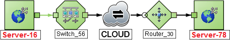
- If a missing connection is detected (no response to SNMP and no entry in
PathConnections.xml), the cloud symbol appears in the routing core between the access routers.
- If the port connecting the end node to the first switch is forwarding more than one MAC address, this indicates an intermediate device (such as a hub or one or more undiscovered switches). A cloud appears at that location in the path.
When interpreting Path View results, note the following:
-
In Path View maps, a black arrow or empty black circle that appears at the end of a connection indicates that NNMi was not able to determine a status value because the connection or interface is not in the NNMi database. Reasons a connection or interface are not stored in the NNMi database, include the following:
- NNMi is unable to collect information about a node in the path because it is a non-SNMP node.
- Not all of the nodes in the path are managed by NNMi.
- The discovery information for a node is not up-to-date (for example, interface information is missing).
- You see only those nodes in the Path View that you have permission to view. NNMi ignores any nodes to which you do not have access and generates the path as if these nodes were not discovered. If you are an NNMi administrator, see Configure Security for more information about configuring security, including node access.
-
The Source and Destination nodes must meet either of the following criteria:
- Support SNMP and be previously discovered by NNMi (recorded in the topology database)
- Have traceroute available
- A switch should not be used as a Source or Destination node in Path View maps. To view connectivity between switches, use the Layer 2 Neighbor View.
-
All access routers and any Layer 2 devices between the Source and Destination nodes must meet the following criteria:
- Support SNMP
- Be previously discovered by NNMi (recorded in the topology database)
- Optional. Each router is monitored by NNMi.
- The time stamp provided in the final Path View is the time at which the final active path was determined.
-
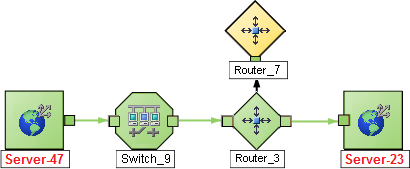
(NNMi Advanced) If the Router Redundancy Group has more than one Active router, NNMi selects one Active router for the path. To indicate there is more than one possible path, NNMi connects any additional Active routers to the chosen router as shown in the following example:
-
(NNMi Advanced) If your network administrator configures NNMi to gather data from Route Analytics Management System (RAMS), the Path View can show multiple OSPFOpen Shortest Path First Protocol Equal Cost paths through a Layer 3 cloud as shown in the example below:
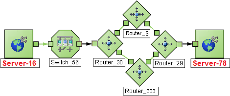
If you are an NNMi administrator, see RAMS MPLS WAN Configuration (NNMi Advanced) for information about configuring RAMS. When RAMS data is used to determine the router paths, NNMi ignores the
PathConnections.xmlfile. - (NNM iSPI Performance for Metrics) You can access performance data from Path Views that contain single or multiple paths. See Investigate Errors and Performance Issues for more information
Path View cannot calculate accurate paths if you have two or more areas of your network which are separated by undiscovered devices. Your NNMi administrator must use the PathConnections.xml file to specify areas of your network that are separated by undiscovered devices. See "Help for Administrators" for more information.
(NNMi Advanced.) Path View works only with IPv4 addresses. The NNMi Advanced IPv6 address values are not valid choices for Path View. Any devices in your network that are configured with IPv6 addresses cannot be displayed on Path View maps.
Path View uses a variety of sources for information to calculate an accurate path. These sources of information do, however, have limitations:
-
SNMP ipRoute tables. If the Source or Destination node represents a device other than a router and the device does not support SNMP or does not return valid ipRoute table information, NNMi depends on traceroute to follow the path to find the nodes's access router.
(NNMi Advanced, plus Route Analytics Management System (RAMS) for MPLS WAN) NNMi can use RAMS data to determine router paths. When RAMS data is used to determine the router paths, NNMi ignores the
PathConnections.xmlfile. See Enhanced Path View () for more information. If you are an NNMi administrator, also see RAMS MPLS WAN Configuration (NNMi Advanced) for more information.Do not specify a switch as a Source or Destination node in Path View maps. To view connectivity between switches, use the Layer 2 Neighbor View.
- Open Shortest Path First protocol or Cisco Global Load Balancing protocol. Path View shows the access router selected by one of these routing protocols. If two or more access routers communicate with a device, only one access router is shown (usually the one with the shortest path).
- Cisco Express Forwarding protocol. This protocol bypasses some of the data that Path View needs. If any routers in the path are using this protocol, Path View might display an incorrect router path.
- If the NNMI administrator enabled MPLSMultiprotocol Label Switching, Path view can show multiple OSPF Equal Cost paths.
Investigate Errors and Performance Issues
The color of the background shape of each map symbol conveys the most recent health status. Select an object on the Path View map that has a status color other than green (see Watch Status Colors for more information about interpreting non-normal status colors). You can access the following types of information about each node:
- Access Node Details
- Access a Problem Device
-
See Interpret Root Cause Incidents for more information about interpreting the incident information displayed.
(NNM iSPI Performance for Metrics) Click here for more information about additional tools for accessing performance data.
Requires Network Node Manager iSPI Performance for Metrics Software (NNM iSPI Performance for Metrics). To populate performance data in the dashboard views or enhance NNM iSPI Performance for Metrics reports by sharing NNMi configuration settings, install the optional Network Performance Server (NPS).
To access performance data from a Path View map:
Select Actions → NNM iSPI Performance → Reporting - Path Health.
If the Path View map contains multiple possible paths from the Source to Destination Node, NNMi alerts and guides you to select a single, unambiguous path for analysis before it can present a Path Health Report. You can bypass this interaction by pre-selecting enough map objects (for example, connections) to resolve any ambiguities before selecting Actions → NNM iSPI Performance → Reporting - Path Health.
(NNMi Advanced) Path View works only with IPv4 addresses. The NNMi Advanced IPv6 address values are not valid choices for Path View. Any devices in your network that are configured with IPv6 addresses cannot be displayed on Path View maps.
Related Topics: