


Layer 2 Connection Form
[This is the Context-Sensitive Help topic for the Layer 2 Connection form.]
The Layer 2 Connection form provides details about a managed connection. These details include the interfaces that make up the connection, the protocol used to create this connection, and the current status of the connection. For example, if all interfaces are down within a connection, the connection status is listed as Critical. The NNMi administrator can configure NNMi to automatically delete Layer 2 Connections when all member Interfaces are down for a specified number of days. This topic includes the following sections:
For information about each tab: ![]() See Also
See Also
Forwarding Database (FDB) information can cause NNMi to establish wrong Layer 2 Connections in the following cases:
- When the FDB is configured as cache and contains obsolete data.
- In network environments with hardware from a variety of vendors, when each vendor generates different and sometimes conflicting FDB data.
Optional: NNMi administrators can configure Spiral Discovery to ignore the FDB data from one Node Group when calculating Layer 2 Connections (the FDB data is still included in other calculations).
(NNMi Advanced - Global Network Management feature) NNMi must read the Forwarding Database (FDB) tables from Ethernet switches within the network before accurate communication paths between these network devices can be calculated. Because the FDB data is involved, NNMi can produce different results on a Regional Manager as opposed to the Global Manager.
| Attribute | Description |
|---|---|
| Name | Name that NNMi assigned to the Layer 2 Connection. This name contains the list of member interface names separated by a comma. Each interface name appears in the format: Node_Name[Interface_Name]. |
| Status |
Overall status for the current connection. NNMi follows the ISO standard for status classification. See the Layer 2 Connection Form: Status Tab for more information. Possible values are:
For information about how the current status was determined, see the Layer 2 Connection Form: Conclusions Tab. Status reflects the most serious outstanding conclusion. See Watch Status Colors for more information about possible status values. The icons are displayed only in table views. |
| Topology Source |
Indicates the data source used to create this connection. (NNMi Advanced) Layer 2 Connections using Link AggregationProtocols used on Switches to configure multiple Interfaces (Aggregation Member Interfaces) to function as if they were one (an Aggregator Interface). When two Aggregator Interfaces establish a connection, that connection is an Aggregator Layer 2 Connection. The Aggregator Layer 2 Connection appears on Layer 2 Neighbor View maps as a thick line with an Interface icon at each end (representing the Aggregator Interface). or Split Link AggregationLink Aggregation with more than two endpoints. Some vendors refer to this as Multi-Chassis Link Aggregation, SLAG, MLAG, or MC-LAG. protocols can connect sets of Interfaces. See Layer 2 Connection Form: Link Aggregation Tab (NNMi Advanced). These Aggregator Layer 2 Connections display as thick lines on NNMi maps. If you see the CDP - Cisco Discovery Protocol. On the NNMi map, the following icon is in the middle of the Layer 2 Connection line: EDP - Extreme Discovery Protocol EnDP - Enterasys Discovery Protocol (also known as CDP - Cabletron Discovery Protocol) FDB - Forwarding Database (also known as AFT - Address Forwarding Table on a switch). On the NNMi map, the following icon is in the middle of the Layer 2 Connection line: FDBH - NNMi’s Forwarding Database High Priority indicates a special case was encountered and NNMi gave priority of FDB over Discovery Protocol information. FDP - Foundry Discovery Protocol IEEELAG - Institute of Electrical and Electronics Engineers Link Aggregation ISL - Inter Switch Link Protocol LLDP - Link Layer Discovery Protocol NDP - IPv6 Neighbor Discovery Protocol SONMP - SynOptics Network Management Protocol VMWARE - VMware VSphere® web-service ROUTES - Indicates that an unnumbered Interface is involved in this connection. The NNMi administrator has enabled the Unnumbered Interface Connectivity feature. For more information: SUBNETCONNECTION
USER - This connection was configured by your NNMi administrator (using the Connection Editor). See "Help for Administrators" for more information. |
| Notes |
(NNMi Advanced - Global Network Management feature) The text you enter here is not sent from a Regional Manager (NNMi management server) to the Global Manager. NNMi administrators for the Global Manager can add notes that are stored in the NNMi database on the Global Manager. Provided for network operators to use for any additional notes required to further explain the Layer 2 Connection. Information might include when a cable was last replaced. Type a maximum of 1024 characters. Alpha-numeric, spaces, and special characters (~ ! @ # $ % ^ & * ( ) _+ -) are permitted. |
 No Status
 Normal
 Disabled
 Unknown
 Warning
 Minor
Minor Major
Major Critical
 icon (in previous NNMi releases the
  icon), NNMi gathered information from Layer 2 of the Open System Interconnection (OSI) networking model to detect this connection. Layer 2 is the Data Link layer that encodes and decodes data packets into bits. The Data Link layer has two sub-layers: The Media Access Control (MAC) sub-layer controls how a computer gains access to data and permission to transmit the data. The Logical Link Control (LLC) sub-layer controls frame synchronization, flow control, and error checking. The following are some examples of possible Topology Source values:
 (in prior NNMi releases, the
  icon)
icon)
[This is the Context-Sensitive Help topic for the Layer 2 Connection form, Interfaces tab.]
The Layer 2 Connection Form provides details about a managed connection. These details include the interfaces that make up the connection, the protocol used to create this connection, and the current status of the connection. For example, if all interfaces are down within a connection, the connection status is listed as Critical.
For information about each tab: ![]() See Also
See Also
|
Attribute |
Description |
|---|---|
|
Interfaces |
Table view of both of the interfaces that are part of the current connection. You can use this table to determine the status, administrative state, operational state, name, type, interface speed, and Layer 2 Connection for each interface associated with the selected Layer 2 Connection. Double-click the row representing an interface. The Interface Form displays all details about the selected interface. |
[This is the Context-Sensitive Help topic for the Layer 2 Connection form, Incidents tab.]
The Layer 2 Connection Form provides details about a managed connection.
For information about each tab: ![]() See Also
See Also
| Attribute | Description |
|---|---|
| Associated Incidents |
Table view of the incidents associated with the selected Layer 2 Connection. NNMi displays only those incidents that have a Family attribute value of To check all Incidents related to the Interface on each end of the connection, navigate to the Layer 2 Connection Form: Interfaces Tab and open an Interface form. To check all incidents related to the Node, use the Hosted On Node attribute on the Interface form to open the Node form. Examples of the incidents that might appear as Associated Incidents for Layer 2 Connections include the following:
Associated Incidents are sorted by creation time so that you can view the incidents in chronological order. Use this view to determine which incidents are still open for the selected connection. Double-click the row representing an incident. The Incident Form displays all details about the selected incident. Navigate to the Incident Form: Correlated Children Tab and Incident Form: Correlated Parents Tab to check for any correlated incidents that are associated with the interfaces and nodes on each end of the connection. |
[This is the Context-Sensitive Help topic for the Layer 2 Connection form, Status tab.]
The Layer 2 Connection Form provides details about a managed connection.
For information about each tab: ![]() See Also
See Also
| Attribute | Description |
|---|---|
| Status History |
List of up to the last 30 changes in status for the selected connection. This view is useful for obtaining a summary of the connection status so that you can better determine any patterns in connection behavior and activity. Double-click the row representing a Status History. The Status History form displays all details about the selected Status. |
[This is the Context-Sensitive Help topic for the Layer 2 Connection form, Conclusions tab.]
The Layer 2 Connection Form provides details about a managed connection.
All relevant conclusions are shown in the table on this tab. The most severe Status in the current group of conclusions becomes the overall L2 Connection status. Some L2 Connection conclusions propagate to other object types: ![]() See Also
See Also
For information about each tab: ![]() See Also
See Also
| Attribute | Description | ||||||||||||||||||||||||||||||||||||||||||||||||||||||||||||||||||||||||||||||||||||
|---|---|---|---|---|---|---|---|---|---|---|---|---|---|---|---|---|---|---|---|---|---|---|---|---|---|---|---|---|---|---|---|---|---|---|---|---|---|---|---|---|---|---|---|---|---|---|---|---|---|---|---|---|---|---|---|---|---|---|---|---|---|---|---|---|---|---|---|---|---|---|---|---|---|---|---|---|---|---|---|---|---|---|---|---|---|
| Outstanding Status Conclusions |
The dynamically generated list of summary statuses of the connection that contributed to the current overall Status of the selected connection. Status is set by Causal Engine. Each Conclusion listed is still outstanding and applies to the current overall Status. This view is useful for obtaining a quick summary of the Status and problem description for the current connection that led up to the connection's most current Status. The Status value is correlated based on the most critical Conclusion. Double-click the row representing a Conclusion. The Conclusion form displays all details about the selected Conclusion. The following table describes the possible Conclusions that might appear for a Connection object. A Y in the Incident? column indicates that the Conclusion results in an incident. Critical Status Conclusions
Minor Status Conclusions
Warning Status Conclusions
Unknown Status Conclusions
Disabled Status Conclusions
Normal Status Conclusions |
||||||||||||||||||||||||||||||||||||||||||||||||||||||||||||||||||||||||||||||||||||
[This is the Context-Sensitive Help topic for the Layer 2 Connection form, Aggregation tab.]
The Layer 2 Connection Form provides details about the selected Layer 2 Connection.
For information about each tab: ![]() See Also
See Also
The Layer 2 Connection Form: Link Aggregation Tab appears if the selected connection uses a Link Aggregation protocol.

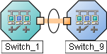
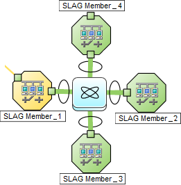
On a Layer 2 map, a thick line with a superimposed ellipse represents a Link AggregationProtocols used on Switches to configure multiple Interfaces (Aggregation Member Interfaces) to function as if they were one (an Aggregator Interface). When two Aggregator Interfaces establish a connection, that connection is an Aggregator Layer 2 Connection. The Aggregator Layer 2 Connection appears on Layer 2 Neighbor View maps as a thick line with an Interface icon at each end (representing the Aggregator Interface). or Split Link AggregationLink Aggregation with more than two endpoints. Some vendors refer to this as Multi-Chassis Link Aggregation, SLAG, MLAG, or MC-LAG. (group of multiple Layer 2 Connections that are functioning as one). The icon representing an Interface at either end of the thick line is an Aggregator Interface (a logical interface comprised of many physical interfaces that are functioning as one).
|
Two endpoints:
|
Three endpoints:
|
More than three endpoints:
|

The selected object's role in the Link Aggregation determines the contents of the tab:
-
Aggregation Member, click here for details.
Attribute Description Link Aggregation Protocol The Link AggregationProtocols used on Switches to configure multiple Interfaces (Aggregation Member Interfaces) to function as if they were one (an Aggregator Interface). When two Aggregator Interfaces establish a connection, that connection is an Aggregator Layer 2 Connection. The Aggregator Layer 2 Connection appears on Layer 2 Neighbor View maps as a thick line with an Interface icon at each end (representing the Aggregator Interface). or Split Link AggregationLink Aggregation with more than two endpoints. Some vendors refer to this as Multi-Chassis Link Aggregation, SLAG, MLAG, or MC-LAG. Protocol currently in use. These protocols allow network administrators to configure a set of interfaces on a switch as one Aggregator Interface, creating an Aggregator Layer 2 Connection to another device using multiple interfaces in parallel to increase bandwidth, increase the speed at which data travels, and increase redundancy:
Text Represents This Protocol Cisco Port Aggregation Protocol Cisco Systems Port Aggregation Protocol (pagp) Nortel Multi-Link Trunking Nortel Multi-Link Trunk technology (mlt) Split MLT Split Multi-Link Trunk: configuration technology (splitMlt) Inter-Switch Trunk MLT Split Multi-Link Trunk: inter-switch trunk (istMlt) 802.3ad Link Aggregation Control Protocol IEEE 802.3ad Link Aggregation Control protocol (LACP) Static/Manual Configured Link Aggregation Static/Manual Configured Link Aggregation Unknown Protocol Link Aggregation unknown It is possible for a Layer 2 Connection to connect sets of Aggregator/Member Interfaces that are configured using different Link Aggregation protocols. In that case, this attribute value contains multiple protocols separated with a slash (/).
nms.topo.core.capability.lag.protocol.PAGP=Cisco Port Aggregation Protocol
nms.topo.core.capability.lag.protocol.MLT=Nortel Multi-Link Trunking
nms.topo.core.capability.lag.protocol.SMLT=Split MLT
nms.topo.core.capability.lag.protocol.ISTMLT=Inter-Switch Trunk MLT
nms.topo.core.capability.lag.protocol.LACP=802.3ad Link Aggregation Control Protocol
nms.topo.core.capability.lag.protocol.STATIC=Static/Manual Configured Link Aggregation
nms.topo.core.capability.lag.protocol.UNKNOWN=Unknown Protocol Link Aggregation
Aggregator Name of the Aggregator that contains the selected participating Aggregation Member:
- Aggregator Interface - represents multiple member interfaces
- Aggregator Layer 2 Connection - thick line on the Layer 2 map represents multiple member Layer 2 Connections
See Layer 2 Neighbor View Map Objects for more information.
Click the
 Lookup icon, and choose
  Open to open the form for the Aggregator.
 -
Aggregator (representing multiple members), click here for details.
Attribute Description Link Aggregation Protocol The Link AggregationProtocols used on Switches to configure multiple Interfaces (Aggregation Member Interfaces) to function as if they were one (an Aggregator Interface). When two Aggregator Interfaces establish a connection, that connection is an Aggregator Layer 2 Connection. The Aggregator Layer 2 Connection appears on Layer 2 Neighbor View maps as a thick line with an Interface icon at each end (representing the Aggregator Interface). or Split Link AggregationLink Aggregation with more than two endpoints. Some vendors refer to this as Multi-Chassis Link Aggregation, SLAG, MLAG, or MC-LAG. Protocol currently in use. These protocols allow network administrators to configure a set of interfaces on a switch as one Aggregator Interface, creating an Aggregator Layer 2 Connection to another device using multiple interfaces in parallel to increase bandwidth, increase the speed at which data travels, and increase redundancy:
Text Represents This Protocol Cisco Port Aggregation Protocol Cisco Systems Port Aggregation Protocol (pagp) Nortel Multi-Link Trunking Nortel Multi-Link Trunk technology (mlt) Split MLT Split Multi-Link Trunk: configuration technology (splitMlt) Inter-Switch Trunk MLT Split Multi-Link Trunk: inter-switch trunk (istMlt) 802.3ad Link Aggregation Control Protocol IEEE 802.3ad Link Aggregation Control protocol (LACP) Static/Manual Configured Link Aggregation Static/Manual Configured Link Aggregation Unknown Protocol Link Aggregation unknown It is possible for a Layer 2 Connection to connect sets of Aggregator/Member Interfaces that are configured using different Link Aggregation protocols. In that case, this attribute value contains multiple protocols separated with a slash (/).
nms.topo.core.capability.lag.protocol.PAGP=Cisco Port Aggregation Protocol
nms.topo.core.capability.lag.protocol.MLT=Nortel Multi-Link Trunking
nms.topo.core.capability.lag.protocol.SMLT=Split MLT
nms.topo.core.capability.lag.protocol.ISTMLT=Inter-Switch Trunk MLT
nms.topo.core.capability.lag.protocol.LACP=802.3ad Link Aggregation Control Protocol
nms.topo.core.capability.lag.protocol.STATIC=Static/Manual Configured Link Aggregation
nms.topo.core.capability.lag.protocol.UNKNOWN=Unknown Protocol Link Aggregation
Available Bandwidth
Sum of the interface Input Speed attribute values of the Member Interfaces that have a MIB-II ifOperStatus that is not
Down. If the sum of the interface Output Speed attribute values is different, NNMi displays separate Available Input Bandwidth and Available Output Bandwidth attributes.Maximum Bandwidth Sum of the interface Input Speed attribute values of the Member Interfaces, regardless of MIB-II
ifOperStatus. If the sum of the interface Output Speed attribute values is different, NNMi displays separate Maximum Input Bandwidth and Maximum Output Bandwidth attributes.Available Bandwidth Percentage Percentage value computed using Available Bandwidth divided by the Maximum Bandwidth. Members Table view of the Aggregation Members.
For more information, double-click the row representing an Aggregation Member:
- The Interface Form displays all details about the selected Interface.
- The Layer 2 Connection Form displays all details about the selected Layer 2 Connection.
[This is the Context-Sensitive Help topic for the Layer 2 Connection form, Registration tab.]
The Layer 2 Connection Form provides details about a managed connection.
For information about each tab: ![]() See Also
See Also
| Attribute | Description |
|---|---|
|
Created |
Date and time the selected object instance was created. NNMi uses the locale of the client and the date and time from the NNMi management server. This value does not change when a node is rediscovered. This is because the Node object is modified, but not created. |
|
Last Modified |
Date the selected object instance was last modified. NNMi uses the locale of the client and the date and time from the NNMi management server. Note the following:
|
| Attribute | Description |
|---|---|
|
ID |
The Unique Object Identifier, which is unique within the NNMi database. |
|
UUID |
The Universally Unique Object Identifier, which is unique across all databases. |